Photovoltaic Cell Using Catalyst-Supporting Carbon Nanotube and Method for Producing the Same

a photovoltaic cell and carbon nanotube technology, applied in nanoinformatics, sustainable manufacturing/processing, final product manufacturing, etc., can solve the problems of limited catalytic activity, small surface area contacting the electrolyte layer, and increasing production costs, and achieve high catalytic activity

Inactive Publication Date: 2008-04-10
SAMSUNG ELECTRONICS CO LTD
View PDF3 Cites 18 Cited by
  • Summary
  • Abstract
  • Description
  • Claims
  • Application Information

AI Technical Summary

Benefits of technology

[0009]An aspect of the present invention includes providing a photovoltaic cell that can be economically f

Problems solved by technology

However, the method for preparing a catalytic metal thin-film or a catalytic metal particle requires a large quantity of catalyst and an additional procedure employing expensive and large-scale vacuum equipment for vacuum deposition, thereby increasing the cost of production.
Further, such methods suffer in that the reaction surface area contacting the elect

Method used


Image

  • Photovoltaic Cell Using Catalyst-Supporting Carbon Nanotube and Method for Producing the Same
  • Photovoltaic Cell Using Catalyst-Supporting Carbon Nanotube and Method for Producing the Same

Examples


preparation example 1

Preparation of a Pt-supported Carbon Nanotube

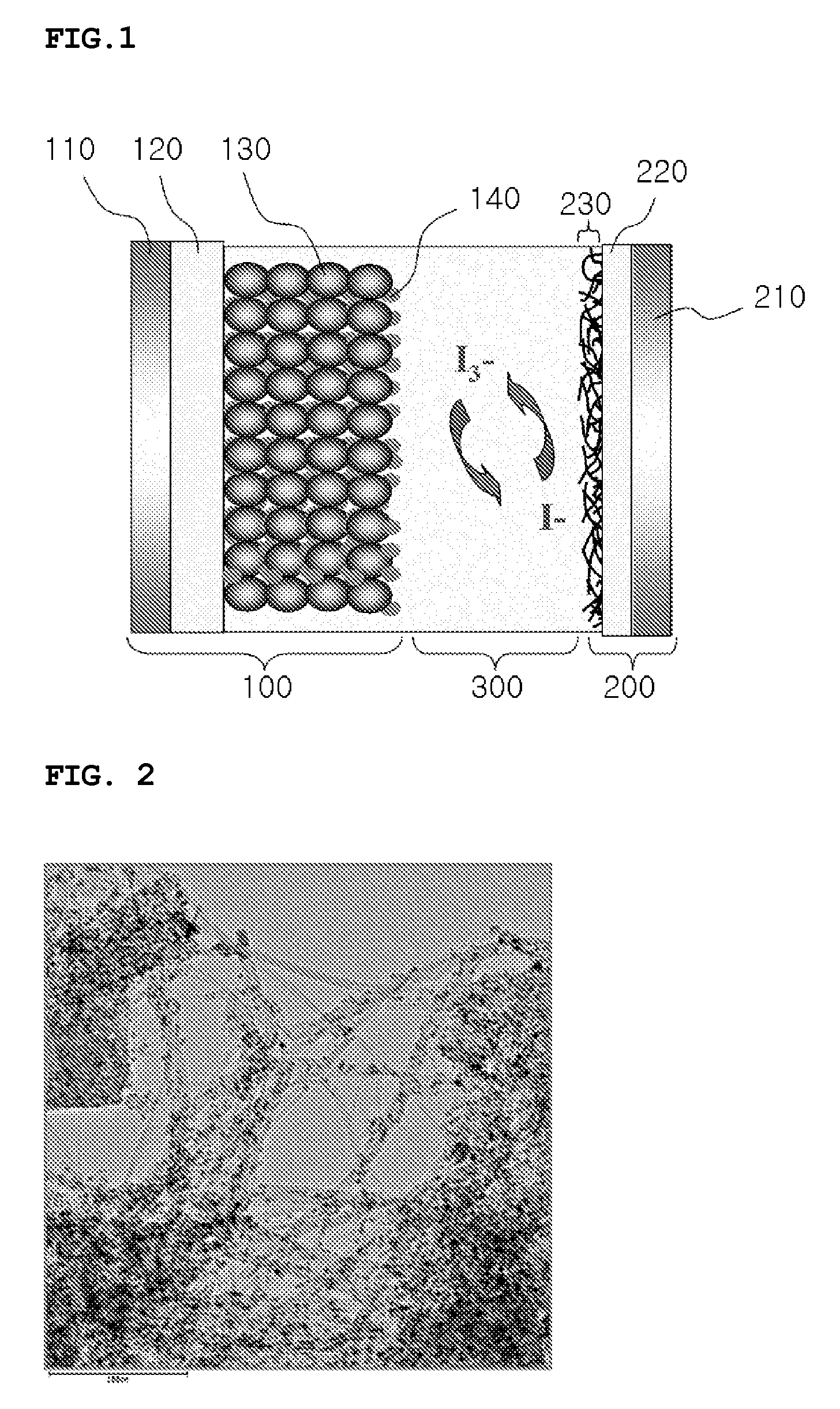
[0051]0.9432 grams (g) of H2PtCl5 were dissolved in about 20 g of ethylene glycol. Separately, about 0.25 g of single wall carbon nanotubes were dispersed in a mixture of about 100 g water and about 80 g of ethylene glycol. The carbon nanotube solution thus prepared was added to the Pt solution, and the mixture's pH was adjusted to about 11 with NaOH. After that, the mixture was allowed to stand at about 105 degrees Celsius (° C.) for about 2 hours, followed by further heating at about 110° C. for about 1 hour to reduce the platinum to metallic platinum and dispose it onto the surface of the carbon nanotubes. After the reaction was complete, the reaction mixture was centrifuged to separate the Pt-supported carbon nanotubes. The Pt-supported carbon nanotubes so separated were washed with water and subjected to lyophilization or freeze-drying. FIG. 2 shows a transmission electron microscope (TEM) image of a representation sample of the Pt-...

preparation example 2

Preparation of a Cathode

[0052]About 0.55 g of the Pt-supported carbon nanotubes prepared in Preparative Example 1, about 0.5 g of glass frit, about 14 g of a binder, and about 15 g terpineol were mixed and uniformly dispersed with a 3-roll mil for about 30 minutes to prepare a paste. Then, a glass substrate coated with FTO was coated with the paste prepared above and dried at about 70° C. for about 30 minutes. Next, the glass substrate was fired at about 430° C. for about 20 minutes under a nitrogen atmosphere, and subjected to a surface treatment to prepare a cathode.

preparation example 3

Preparation of a Cathode

[0053]A cathode was prepared according to the same method as described in Preparation Example 2 except for an additional step of activation the coated carbon nanotube through mechanical activiation.


PUM


Abstract

Disclosed herein is a photovoltaic cell using catalyst-supported carbon nanotubes and a method for producing the same. More particularly, the photovoltaic cell includes a photo anode, a cathode including a layer of metal catalyst particle supporting carbon nanotubes, and an electrolyte disposed between the photo anode and the cathode. The photovoltaic cell is economic in terms of production costs and process steps, and shows improved catalytic activity due to an enlarged contact area and conductivity, resulting in excellent photoelectric efficiency.

Description

[0001]This nonprovisional application claims priority to Korean Patent Application No. 10-2006-0065835, filed on Jul. 13, 2006, and all the benefits accruing therefrom under 35 U.S.C. §119, the contents of which are herein incorporated by reference in its entirety.BACKGROUND OF THE INVENTION [0002]1. Field of the Invention[0003]The present invention relates to a photovoltaic cell using a catalyst-supporting carbon nanotube and a method for producing the same. More particularly, the present invention relates to a photovoltaic cell which can be easily produced by a simple and economic process using a carbon nanotube containing metal catalyst particles supported thereon, and a method for producing the same.[0004]2. Description of the Related Art[0005]In order to overcome energy problems that have been recently confronted, various research on alternative energy sources capable of replacing the existing fossil fuel are actively underway. In particular, for the replacement of oil resource...

Claims


Application Information

Patent Timeline
IPC IPC(8): H01L31/00
CPCB82Y10/00H01G9/2022H01G9/2031Y02E10/549H01L51/0086H01L51/444Y02E10/542H01L51/0048Y02E10/547Y02P70/50H10K85/221H10K85/344H10K30/821C01B32/158B82Y40/00H01L31/0224H01L31/042H01L31/1804C01B2202/34C01B2202/36C01B2202/02C01B2202/04
Inventor PARK, YOUNG JUNLEE, EUN SUNGLEE, JEONG HEEPARK, SANG CHEOLNAM, JUNG GYU
Owner SAMSUNG ELECTRONICS CO LTD
Why Eureka
Try Eureka