Regenerative energy storage system for hybrid locomotive

a technology of regenerative energy storage and hybrid locomotives, which is applied in the direction of locomotives, braking systems, transportation and packaging, etc., can solve the problems of increasing vehicle weight and energy, increasing the cost and size of the battery pack, and reducing the efficiency of the vehicle, so as to avoid conversion losses, facilitate packaging and allowance of greater accumulator volume, and save costs

Inactive Publication Date: 2008-04-10
READ DAVID H
View PDF30 Cites 31 Cited by
  • Summary
  • Abstract
  • Description
  • Claims
  • Application Information

AI Technical Summary

Benefits of technology

[0009]It is also an object of the invention to provide improved methods of operation to improve the cost-effectiveness for the reduction of fuel consumption in such vehicles.SUMMARY OF THE INVENTION
[0013]In a third embodiment of the present invention, a diesel-hydraulic locomotive for use with hydraulic energy storage is provided. A diesel-hydraulic locomotive is used instead of a diesel-electric locomotive to avoid conversion losses involved in converting between electrical and hydraulic energy in the above embodiments. Thus, in this embodiment, a main internal combustion engine of the locomotive drives a first hydraulic pump / motor as a pump to provide pressurized fluid to drive one or more hydraulic pump / motors as motors for propulsion. The first pump / motor and drive pump / motors may operate together much as a hydrostatic transmission, as is known in the art. One or more high pressure accumulators are provided for storage of pressurized fluid from either the first hydraulic pump / motor (driven by the engine) or the drive hydraulic pump / motors (e.g., when used for regenerative “braking” or slowing).
[0014]The accumulators may be stored on a separate energy storage car for easier packaging and allowance of greater accumulator volume. An APU (e.g., a separate small diesel engine running an electric generator) is optionally further provided to enable efficient generation of auxiliary power for accessories or other needs at idle or low power conditions, where operation of the main engine is then made unnecessary.
[0015]Great cost savings may be achieved with the present invention by enabling substitution of the energy storage cars or locomotives of the present invention for one or more of multiple locomotives used for freight train routes. This could be done on a route-by-route basis. The energy storage car could be sized to be of comparable size to a locomotive and to deliver comparable horsepower when needed. The savings in not needing one locomotive, and to redeploy the locomotive for other use, is significant.
[0016]Methods for energy recovery at long grades are also provided. In a first method, energy recovery stations are placed at hills to collect energy from, and supplement energy to, the locomotives. Existence of such stations at long grades would allow for more efficient design of on-board energy storage systems, which would thus need sufficient energy storage capacity for recovery and supplementation for regular braking and coasting, and not the higher requirements for handling long grades. In a second method, ascension of grades with a reduced number of diesel locomotives may be facilitated by phased ascension, comprising a period of ascension supplemented by energy storage, applying brakes and stopped ascension while the energy storage is system is recharged by operation of the combustion engine, and then continued ascension supplemented by energy storage, until ascension of the grade is completed.

Problems solved by technology

Two principal drawbacks for hybrid electric powertrains for heavy vehicles are that the storage batteries for such powertrains are expensive, and that current batteries which are not completely cost-prohibitive are severely limited in their ability to quickly capture and store large bursts of energy such as may occur in attempted regenerative braking of a heavy or fast-moving vehicle: As a result, with state of the art hybrid electric technology, a typical hybrid electric passenger car is able to recover and re-use on average only about one-third or less of its kinetic energy lost in braking, a typical prototype heavy-duty hybrid electric truck or bus can recover and re-use only about 15-20% of its kinetic energy lost in braking, and an extremely heavy vehicle such as a hybrid electric locomotive with freight would be expected to recover and re-use only a very small percentage of its kinetic energy in braking.
The cost and size of the battery pack needed also greatly increases with the increase in vehicle weight and energy to store.
In addition, the ability to significantly buffer engine operation (i.e., maintain engine operation at good efficiency levels through use of the secondary power system to add or subtract power to the engine output) is also limited for hybrid electric powertrains where the engine is large (again because of the limited efficient charge / discharge rates for batteries which reduce efficiency and durability when charging or discharging at high power levels), such as in heavy vehicles, trains or locomotives.

Method used


Image

  • Regenerative energy storage system for hybrid locomotive
  • Regenerative energy storage system for hybrid locomotive
  • Regenerative energy storage system for hybrid locomotive

Examples


Embodiment Construction

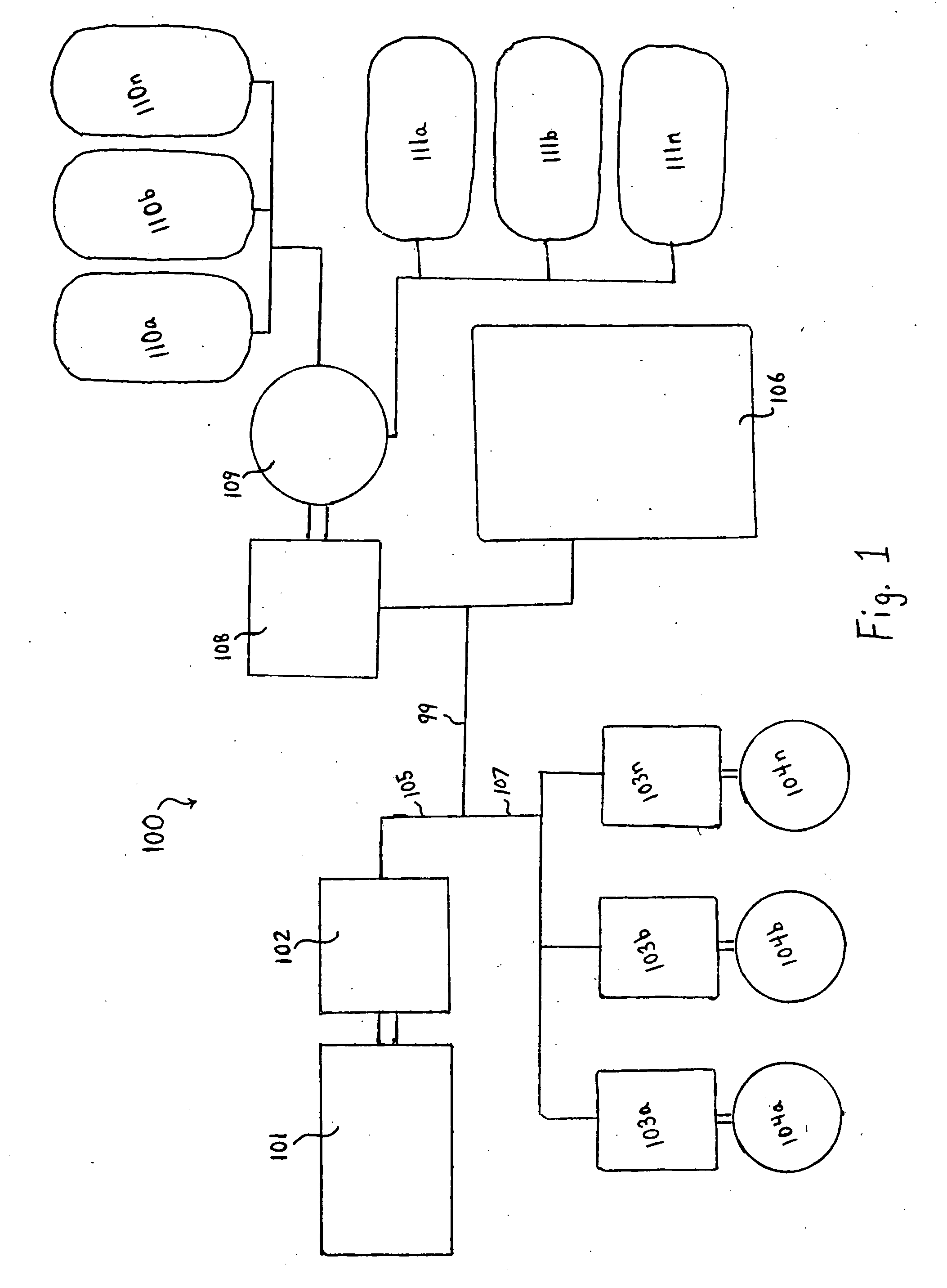
[0027]FIG. 1 is a schematic diagram of a powertrain of the present invention for use in conjunction with a diesel-electric locomotive.

[0028]Referring to FIG. 1, in diesel-electric locomotive 100, an internal combustion engine 101 drives a first main electric / motor generator 102 to provide electric current through lines 105 and 107 to drive multiple electric motor / generators 103a, 103b . . . to 103n, as motors to drive wheels 104a, 104b . . . to 104n of the locomotive. Any actual number of motors and / or wheels may be used. Propulsion of the locomotive is performed as a known diesel-electric locomotive.

[0029]In dynamic braking, electrical power generated by the traction motors 103a-n is routed to motor / generator 108, which then operates as a motor to mechanically drive hydraulic pump / motor 109 as a pump. When driven by motor 108, pump / motor 109 pumps fluid from low pressure accumulators 110a-n to a bank of high pressure accumulators 111a-n, for additional storage of energy. Any number...


PUM


Abstract

An energy storage car for a locomotive includes a hydraulic energy storage system designed to capture and reuse energy normally lost in dynamic braking. The energy storage car is preferably configured to provide functions sufficient to replace one of multiple locomotives used to pull a freight train. Braking methods, and methods to capture and reuse dynamic braking energy on long grades, for such trains are provided.

Description

CROSS-REFERENCE TO RELATED APPLICATIONS[0001]This application claims priority to U.S. provisional application 60 / 849,286, filed Oct. 4, 2006.FIELD OF THE INVENTION[0002]The present invention relates to regenerative energy storage systems, particularly to those adapted for use with very heavy vehicles, such as hybrid trains or locomotives.DESCRIPTION OF THE RELATED ART[0003]Hybrid powertrains have been investigated as a means to reduce fuel consumption and reduce harmful emissions. Hybrid electric powertrains are the most commonly investigated hybrid vehicle powertrain. Hybrid electric powertrains have been found capable of reducing fuel consumption and harmful emissions in some applications, with certain drawbacks.[0004]Two principal drawbacks for hybrid electric powertrains for heavy vehicles are that the storage batteries for such powertrains are expensive, and that current batteries which are not completely cost-prohibitive are severely limited in their ability to quickly capture...

Claims


Application Information

Patent Timeline
Patent Type & Authority Applications(United States)
IPC IPC(8): B60K6/20B60T13/00
CPCB60T1/10Y02T30/10B61C7/00Y02T30/00
Inventor READ, DAVID H.
Owner READ DAVID H
Why Eureka
Try Eureka