Color display, liquid crystal display, and translucent liquid crystal display

a liquid crystal display and color display technology, applied in the field of color display devices, can solve the problems of increasing the number of subpixels, increasing the number of electrical wiring lines associated therewith, and reducing the image resolution, and achieve the effect of suppressing the image resolution reduction

Active Publication Date: 2008-04-10
JAPAN DISPLAY INC +1
View PDF7 Cites 107 Cited by
  • Summary
  • Abstract
  • Description
  • Claims
  • Application Information

AI Technical Summary

Benefits of technology

[0017]According to this invention, by adding white (W) pixels without having to increase the wiring line number, the loss occurring due to the presence of a color filter(s) is lessened to thereby make it possible to provide a display device with suppressibility of the image resolution reduction and also provide information terminal equipment using such the device.

Problems solved by technology

Although the addition of white (W) subpixels for reducing the color absorption loss due to color filters is effective, merely adding white (W) subpixels to red (R), green (G) and blue (B) subpixels causes a total number of subpixels to increase, resulting in an increase in number of electrical wiring lines associated therewith.
When fixing this problem by use of the technique as taught by the above-cited US 2005 / 0225575A1, another problem arises as to a decrease in image resolution because of the fact that a per-color pixel number in the lateral direction is set to one-half of that of the parallel layout of extra-fine red (R), green (G) and blue (B) subpixels.
However, in middle or high definition display devices with the resolution being set at 200 ppi, or more or less, the penalty appreciably degrades the viewability and visibility of on-screen color images.

Method used


Image

  • Color display, liquid crystal display, and translucent liquid crystal display
  • Color display, liquid crystal display, and translucent liquid crystal display
  • Color display, liquid crystal display, and translucent liquid crystal display

Examples


embodiment 1

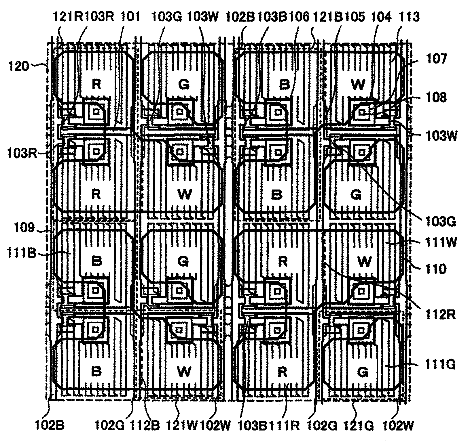
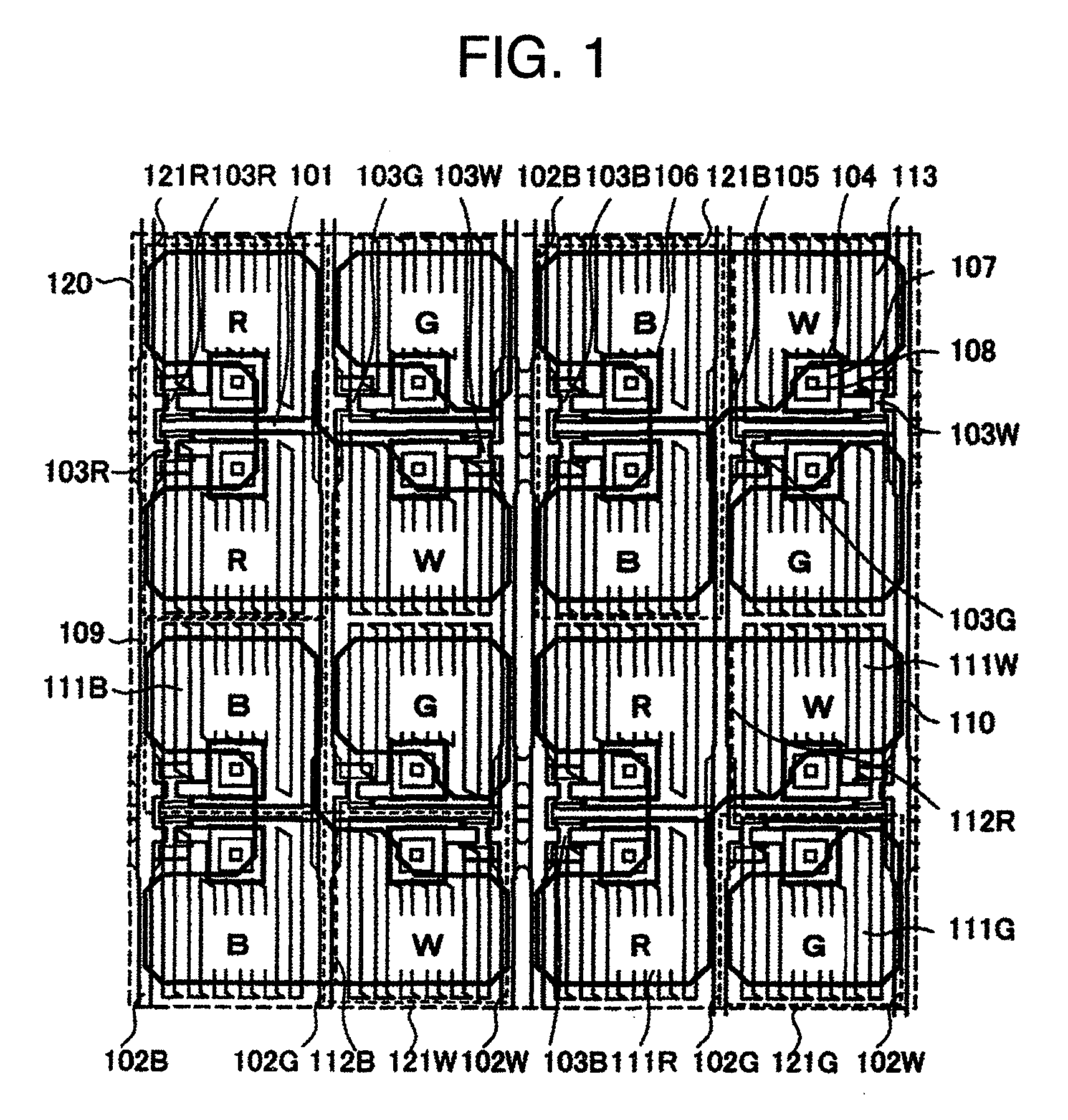
[0032]A configuration of this embodiment will be described by use of FIG. 1. FIG. 1 is an enlarged plan view of part of a display device of this embodiment, including a plurality of picture elements or “pixels” in a display area with a matrix array of pixels each made up of sub-pixels being provided in units of colors. The display device of this embodiment is a liquid crystal display (LCD) device, which is arranged so that a liquid crystal (LC) layer is filled between a first substrate on which a plurality of thin-film transistors (TFTs) provided on a per-subpixel basis and wiring lines are disposed in a matrix form and a second substrate with color filters and a black matrix being disposed thereon. The LCD device is of the type using the so-called active matrix drive technique. Optical films, such as polarization plates, are bonded onto specified surfaces of the first and second substrates, which surfaces are on the opposite side to the LC layer. The display device of this embodime...

embodiment 2

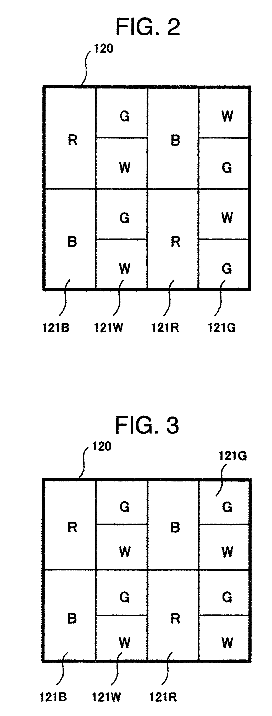
[0051]Regarding peripheral circuit design in a case where the unit subpixel configuration is not employed, this embodiment provides a solution to problems occurrable in the pixel layouts shown in FIGS. 2 and 3 when failing to use the unit subpixel arrangement and thus resulting in the subpixels being different in size on a per-color basis, which solution is different from that of the embodiment 1. One problem occurring in case the subpixels are different in size on a per-color basis is that the optimum common voltage becomes different in its potential value due to a difference of feed-through voltage on a per-subpixel basis, which can occur due to differences of each subpixel's electrical characteristics (e.g., retained capacitance, parasitic capacitance or else). Size-different subpixels will be referred to as a first kind of subpixel and second kind of subpixel, respectively. A method for supplying color-tone or gradation voltages which are optimized to the first kind of subpixel ...

embodiment 3

(RGBC Layout)

[0059]In this embodiment, a description will be given of another configuration of color filters in the subpixel layouts shown in FIGS. 2 and 3. While the embodiments shown in FIGS. 2-3 are each arranged to have white (W) subpixels in addition to the subpixels of three primary colors, i.e., red (R), green (G) and blue (B), this arrangement may be modified so that the green (G) and white (W) subpixels which are higher in visual sensitivity than red (R) and blue (B) subpixels are replaced by subpixels of blue-blended green (CG) and yellow-blended green (YG) which are similarly high in visual sensitivity to thereby provide a configuration of four primary colors as shown in FIGS. 8 and 9. An advantage of this arrangement lies in its ability to widen the range of color reproduction when compared to the case of using only three primary colors, i.e., red (R), green (G) and blue (B). Very importantly, the advantage as to expandability of the color reproduction range is obtainabl...


PUM


Abstract

In a color display device, when using white (W) sub-pixels in addition to subpixels of red (R) and green (G) plus blue (B) without increasing a wiring line number, the per-color pixel number in a unit area decreases so that the image resolution is deteriorated. The area and number of subpixels are adjusted in accordance with the visual sensitivity or luminosity required. Practically, the area of red (R) and blue (B) subpixels which are relatively low in luminosity is set to be about two times greater than the area of green (G) and white (W) subpixels that are relatively high in luminosity while letting the number of green (G) and white (W) subpixels be twice the number of red (R) and blue (B) subpixels. A larger subpixel is configured from a plurality of unit subpixels. A smaller subpixel is formed of a one unit subpixel.

Description

BACKGROUND OF THE INVENTION[0001]The present invention relates to a color display device for displaying images, a liquid crystal display (LCD) device, and a semi-transmissive LCD device.[0002]Currently available color display devices for use in practical applications include devices based on various kinds of display technologies, such as cathode ray tube (CRT) monitors, liquid crystal display (LCD) devices, plasma display panels (PDPs), organic light-emitting diode (LED) panels, field emission display (FED) panels, and electrophoresis or electrochrominance-based electronic paper (“e-paper”) display panels. A major approach to achieving color image displaying in non-emissive LCDs is to use a technique for arranging a picture element or “pixel” by a parallel layout of sub-pixels having color filters of the three primary colors, i.e., red (R), green (G) and blue (B), and for adjusting the brightness of each subpixel independently of one another to thereby represent any given color by a...

Claims


Application Information

Patent Timeline
Patent Type & Authority Applications(United States)
IPC IPC(8): G09G3/36
CPCG09G3/2074G09G3/3607G09G3/3648G09G2320/0276G09G2300/0456G09G2320/0219G09G2320/0233G09G2300/0452G02F1/1335G02F1/133514G02F1/134309H10K59/351H10K59/353G02F1/136286G09G3/2003
Inventor HIROTA, SHOICHIKOMURA, SHINICHISEKIGUCHI, YOSHIFUMIYAMAMOTO, TSUNENORIADACHI, MASAYA
Owner JAPAN DISPLAY INC
Why Eureka
Try Eureka