
System, method, and apparatus for hybrid dynamic shape buoyant, dynamic lift-assisted air vehicle, employing aquatic-like propulsion

a dynamic lift and air vehicle technology, applied in the field of hybrid dynamic shape changing buoyant lift-assisted air vehicles, can solve the problems of prohibitive market entry shortcomings of conventional passenger and cargo airships, the daily utility or accessibility of the general public, and the sky remains virtually empty of comparable practical, utilitarian public and personal daily use aircraft. , to achieve the effect of reducing the risk of accidents

Inactive Publication Date: 2008-04-17
HOLLOMAN RICHARD +1
View PDF28 Cites 95 Cited by
  • Summary
  • Abstract
  • Description
  • Claims
  • Application Information

AI Technical Summary

Benefits of technology

[0017] The purpose of the present invention is to provide a new type of air vehicle accessible to both the general public and for special purpose uses, and system and method thereof, for point-to-point flight requiring minimal ground infrastructure that is safe, economical, quiet, easy to operate, and compatible with current airspace safety regulations. In particular, the present invention relates to intuitive controlled reconfiguration of the best elements of winged air vehicles coupled with variable buoyant lift and bio-inspired empennage and fin / fluke oscillation which enable full-freedom vertical and horizontal flight operations. This modular, hybrid, morphing dynastat air vehicle offers novel aviation capabilities that include exceptional flight upset prevention and recovery characteristics and unique tether operations.
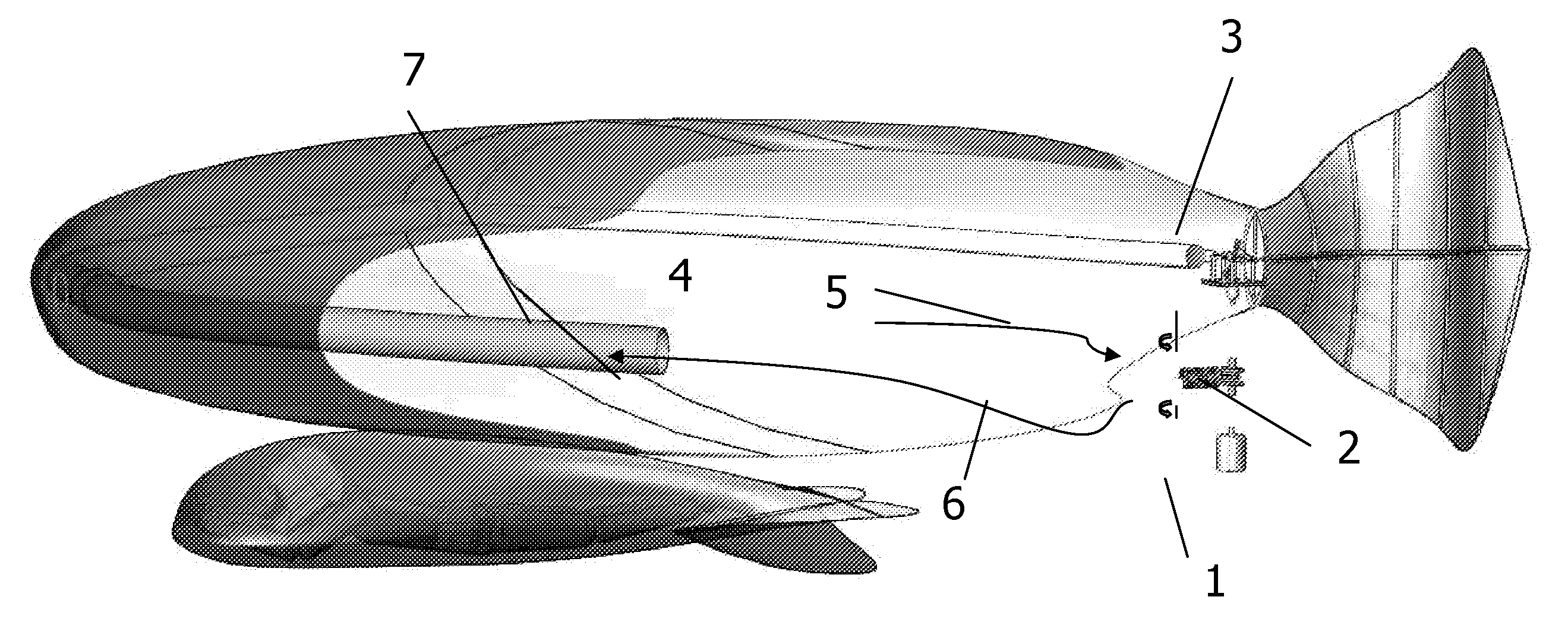
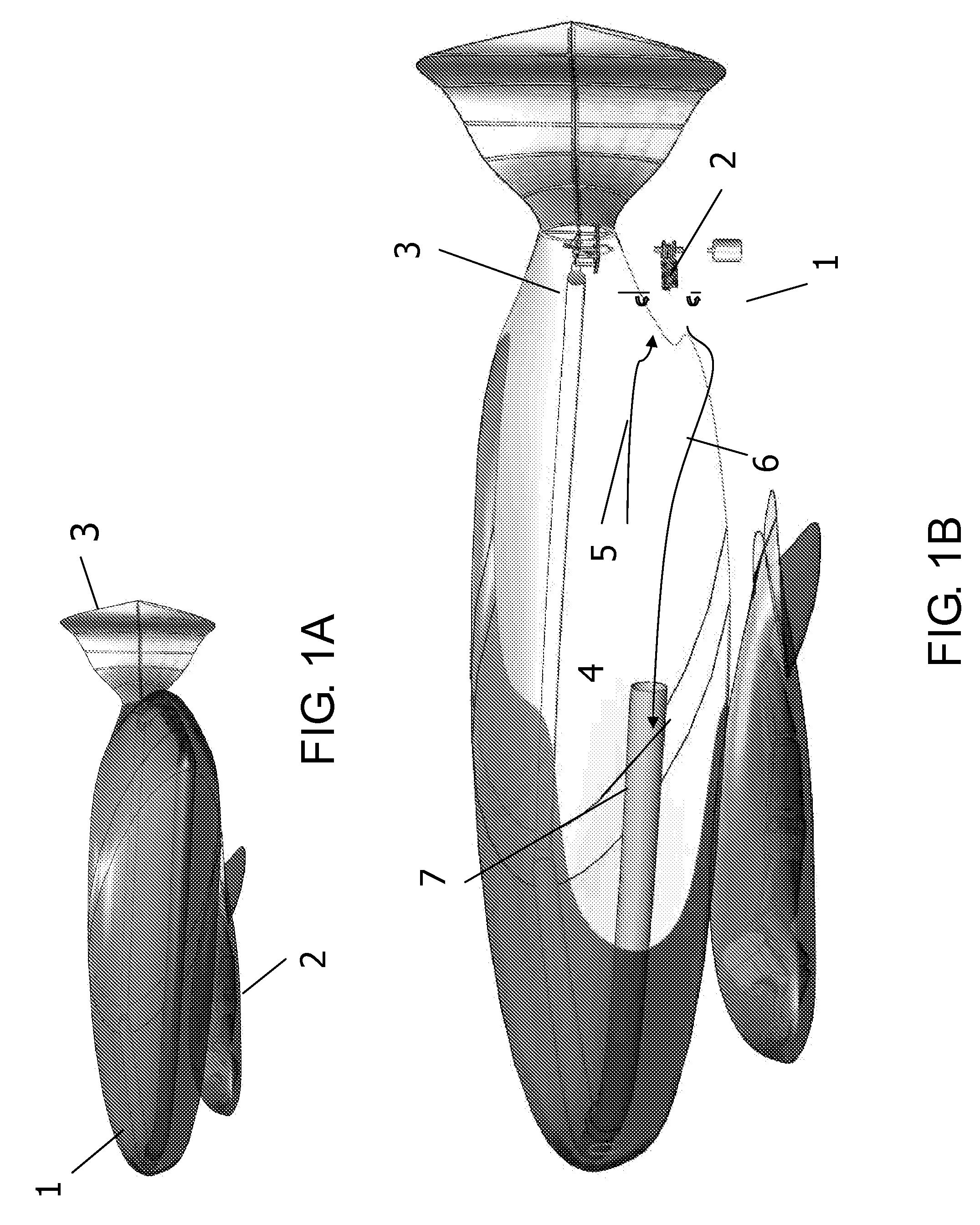
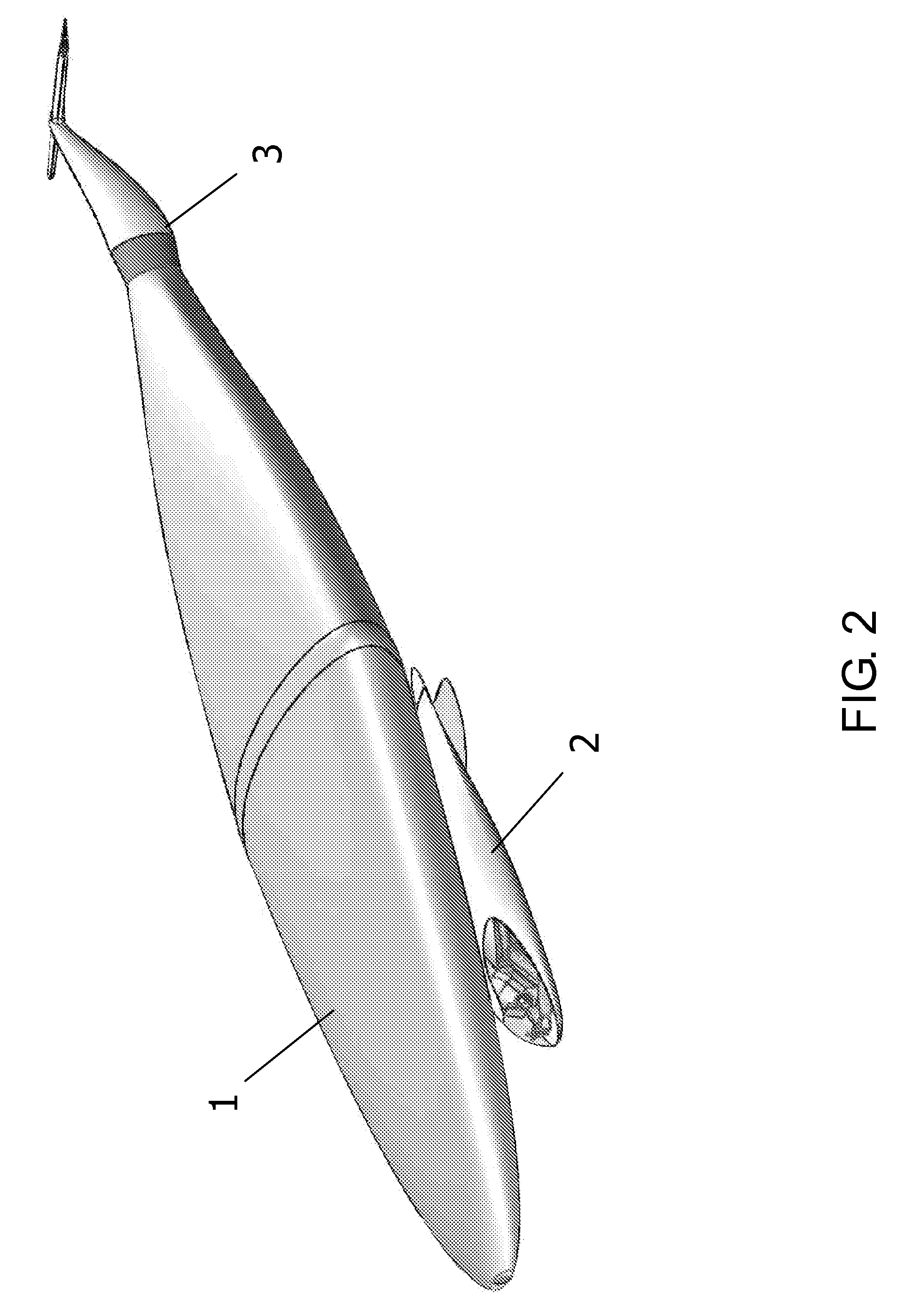
[0018] The present invention comprises a lift module, an empennage propulsion module, and a payload module. In most embodiments of the invention, each module comprises mechanisms taught herein for controlled, dynamic changes in shape to optimize vehicle safety and quiet efficiency. Likewise with the exception of small hybrid unmanned and human powered variants of the invention, each module of most embodiments is at least partially lift gas-filled, thereby contributing buoyant lift to the total vehicle. Each comprises internal and external reconfiguration structures as taught herein, and each (with the same exceptions) is generally encapsulated by commercially available strong impermeable flexible skin to enable low-drag effectual morphing buoyant lift-assisted flight. The present invention employs commercially available means (including hook and fastener) for rapid ability to release of the modules from each other, allowing on-ground swapping of various embodiments or subcomponents of each module. Crucial to the present invention's rapid adoption and public success is its readiness for safe operations over residential and high interest areas and its response as taught herein to conventional FAA certified aircraft control system 2-axis and 3-axis yoke and pedal inputs. Designed for safe operation in the most demanding national airspace, including takeoff, landing, changing direction, moving forward, and hovering in the air, this integrated vehicle is largely inspired by buoyant and semi-buoyant aquatic animals swimming in water. Direct feedback pressurized air beam skeletal mechanisms facilitate the dramatic shape transformations needed for progressive stages of variable buoyant lift-assisted flight.

Problems solved by technology

Despite extensive early aviation use of airships and more than a century of aviation advances nearly paralleling the evolution of the automobile, the sky today remains virtually empty of comparable practical, utilitarian public and personal daily use aircraft, especially buoyant lift-assisted air vehicles.
Notwithstanding vertical lift and runway-free operational advantages, conventional passenger and cargo airships still suffer prohibitive market entry shortcomings.
Conventional fixed and rotary wing aircraft capable of carrying passenger loads comparable to autos remain largely the domain of wealthy businesses or recreational users and of limited daily utility or accessibility for the general public, even for public needs such as law enforcement, search and rescue, disaster response and resource management.
The large surface area skin friction and drag of legacy lighter-than-air (LTA) vehicles limit their operational altitude, speed, and aerodynamic load and render them vulnerable to winds and electrical storms especially during takeoff and landing.
Lift gas logistics and costs and low / medium altitude atmospheric factors have historically rendered LTA craft impractical, unsafe, and too expensive for airlift of humans in an urban environment or for high altitude payload operations.
In short, existing buoyant lift-assisted air vehicles are still too large, cumbersome and slow for most aviation operations, especially for personal travel, and dynamic lift (winged) air vehicles will not soon be found in traditional commuter driveways.
Travelers desiring convenient point-to-point air transportation today remain primarily limited to conventional fixed and rotary winged aircraft variants.
The rigid vehicle superstructure is relatively confining, fragile and inherently vulnerable to catastrophic upset, especially during loss of lift or control induced by an engine or pilot incident.
In the heyday of airships, however, passengers experienced LTA craft as stable, comfortable, and inherently safe—only too slow, costly, and large, especially for private use.
These air vehicles must in turn be stored and operated at locations offering specialized support infrastructure typically some distance away from payload origin, resulting in extra total trip time and operating expense.
Propulsion mechanisms for conventional fixed and rotary wing solutions are typically complex, expensive, noisy, require frequent specialized maintenance, and burn volatile toxic fuels—and LTA propulsion is only marginally better.
Among such prior art attempts to solve the above mentioned problems, none has managed to fully exploit recent advances in materials and processing power that now allow precision bio-inspired empennage and fin / fluke oscillation as a method of propulsion and a synergistic shape-morphing, hybrid buoyant lift-assisted aerodynamic winged air vehicle.

Method used


Image

  • System, method, and apparatus for hybrid dynamic shape buoyant, dynamic lift-assisted air vehicle, employing aquatic-like propulsion
  • System, method, and apparatus for hybrid dynamic shape buoyant, dynamic lift-assisted air vehicle, employing aquatic-like propulsion
  • System, method, and apparatus for hybrid dynamic shape buoyant, dynamic lift-assisted air vehicle, employing aquatic-like propulsion

Examples


Embodiment Construction

[0179] An important feature illustrated by nearly all the drawings of the present invention, in particular FIGS. 1a, 1b, and 2 is the vehicle's modularity using conventional means of universal interoperable attachment and detachment of the various components—useful for flexibility in operations, ease in upgrades, and simplicity in maintenance. Not only are variants of the three primary modules interchangeable according to user preferences, but components of the modules are also highly variable in design and function for combination with conventional off the shelf systems.

[0180] The morphing lift module (FIGS. 3-11) comprises a pneumatically deployable flexible air beam skeletal system (see FIGS. 14, 15) that controls the infinitely variable deployment, redeployment, dimensions and rigidity of the module's left and right wing segments (FIGS. 5, 8, and 9) and central body expansion envelope (FIGS. 6, 7). When configured to favor dynamic flight (FIGS. 8,9), the air beams (FIGS. 15a-e)...


PUM


Abstract

A method and system for air flight is shown. The blended lifting body system includes a lift module, a propulsion module, a payload module and a control system. A conventional control system morphs the other modules through variable buoyant lift, internal structures and a flexible exterior, and varies bio-inspired oscillation in the propulsion module in order to facilitate takeoff, flight and landing. The hybrid dynamic / morphing shape buoyant, dynamic lift-assisted (hybrid) air vehicle, employing aquatic-like (e.g. fin) propulsion was discussed, with many variations and examples.

Description

RELATED APPLICATIONS [0001] This application is the CIP of the co-pending application Ser. No. 11 / 230,695, filed Sep.-20-20005, with some common inventor, and same assignee.FIELD OF THE INVENTION [0002] The present invention relates to the field of hybrid shape-changeable buoyant lift-assisted winged air vehicles capable of both high speed point-to-point flight and extended duration station-keeping flight. By exploiting recent advances in materials and propulsion technology, the invention combines extreme-scale reconfigurations of aerodynamic shape with bio-inspired empennage and fin / fluke oscillation mechanisms to offer unprecedented safety, economy, duration, range and simplicity of variable-vector lift air transportation. BACKGROUND OF THE INVENTION [0003] Despite extensive early aviation use of airships and more than a century of aviation advances nearly paralleling the evolution of the automobile, the sky today remains virtually empty of comparable practical, utilitarian public...

Claims


Application Information

Patent Timeline
Patent Type & Authority Applications(United States)
IPC IPC(8): B64B1/00
CPCB64C1/0009B64B2201/00Y02T50/12B64C2001/0045Y02T50/10B64B1/12B64U10/30B64U30/40B64U80/84B64U30/12B64U80/86B64U50/11B64U80/82
Inventor HOLLOMAN, RICHARDPEERY, TIMOTHY
Owner HOLLOMAN RICHARD
Learn More