Mold for producing an article

a technology for producing articles and molds, applied in the direction of ceramic shaping apparatus, building parts, building parts, etc., can solve the problems of prototypes that do not have exact properties, casts that cannot be easily changed in their design, and molds that do not allow high pressure molding, etc., to achieve accurate and precise molds, adjust or enhance the properties of mold matrix materials, and accurate and precise effects

Inactive Publication Date: 2008-04-17
ELECTROVAC
View PDF13 Cites 13 Cited by
  • Summary
  • Abstract
  • Description
  • Claims
  • Application Information

AI Technical Summary

Benefits of technology

[0032] Preferably, the pressure to harden the mold matrix material can be less than 1000 psi, preferably in a range between 500 to 800 psi. This also results in a very accurate and precise mold.
[0033] According to a further feature of the present invention the method may further comprise the step of mixing to the liquid phenolic resin a filler material, which, or at least part thereof, is made preferably of a metal, a precious metal, a ceramic, other materials, e.g. aluminium, copper, titanium, aluminium nitride, boron nitride, silicon nitride, steel fibers and / or graphite flakes. By choosing proper filler materials it is possible to adjust or enhance the properties of the mold matrix material. These properties include hardness, rigidity, electrical and thermal conductivity, heat capacity, etc.
[0034] According to another feature of the present invention, the content of catalyst may be less than 5 wt % of the total weight of phenolic resin and catalyst. This rather small amount of catalyst will result in an even more accurate and precise mold with exact proportions.
[0035] Preferably, the method can be performed with the carbon fibers including carbon nano fibers. As already stated above, it has been found out that the presence of carbon nano fibers in the mold matrix material dramatically improves the mechanical properties of the material. A mold matrix material made according to the inventive method from phenolic resin comprising carbon nano fibers is significantly less prone to break or tear. However, it still retains its hard surface and high rigidity.
[0036] Advantageously, the mold matrix material can include at least two types of carbon fibers, one type of which including carbon nano fibers. Using both carbon fibers and carbon nano fibers results in less cost but still in a mold having the outstanding properties resulting from the carbon nano fibers.
[0037] According to another feature of the present invention, the step of mixing can be performed to obtain a homogenous mixture of the at least two types of carbon fibers. This allows production of the mold in a single step and results in material properties that are uniform over the whole matrix material.

Problems solved by technology

However, steel molds cannot easily be changed in their design which makes them unfavorable during prototyping or the pre-production phase.
These casts do, however, not allow high pressure molding.
This results in prototypes that do not have the exact properties of the later product which will then be cast in a steel mold.
While these molds make quick changes in the design of the prototype possible, they are subject to quite severe pressure limitations.
If casting is performed at high pressure these molds tend to wear and break and are therefore not capable of being used several times.
While these molds have led to progress in the field of rapid prototyping their use is still limited to the prototyping phase.
One reason for this is that they still tend to wear so that only a small number of products may be produced with one mold.
Another reason is their drawback that products made within these molds cannot fulfill the requirements of surface properties expected from customers.
Due to their surface roughness labor-intensive surface finishing would have to be made if these products should be sold in a large scale.

Method used


Image

  • Mold for producing an article
  • Mold for producing an article
  • Mold for producing an article

Examples


Embodiment Construction

[0048] Throughout all the Figures, same or corresponding elements are generally indicated by same reference numerals. These depicted embodiments are to be understood as illustrative of the invention and not as limiting in any way. It should also be understood that the figures are not necessarily to scale and that the embodiments are sometimes illustrated by graphic symbols, phantom lines, diagrammatic representations and fragmentary views. In certain instances, details which are not necessary for an understanding of the present invention or which render other details difficult to perceive may have been omitted.

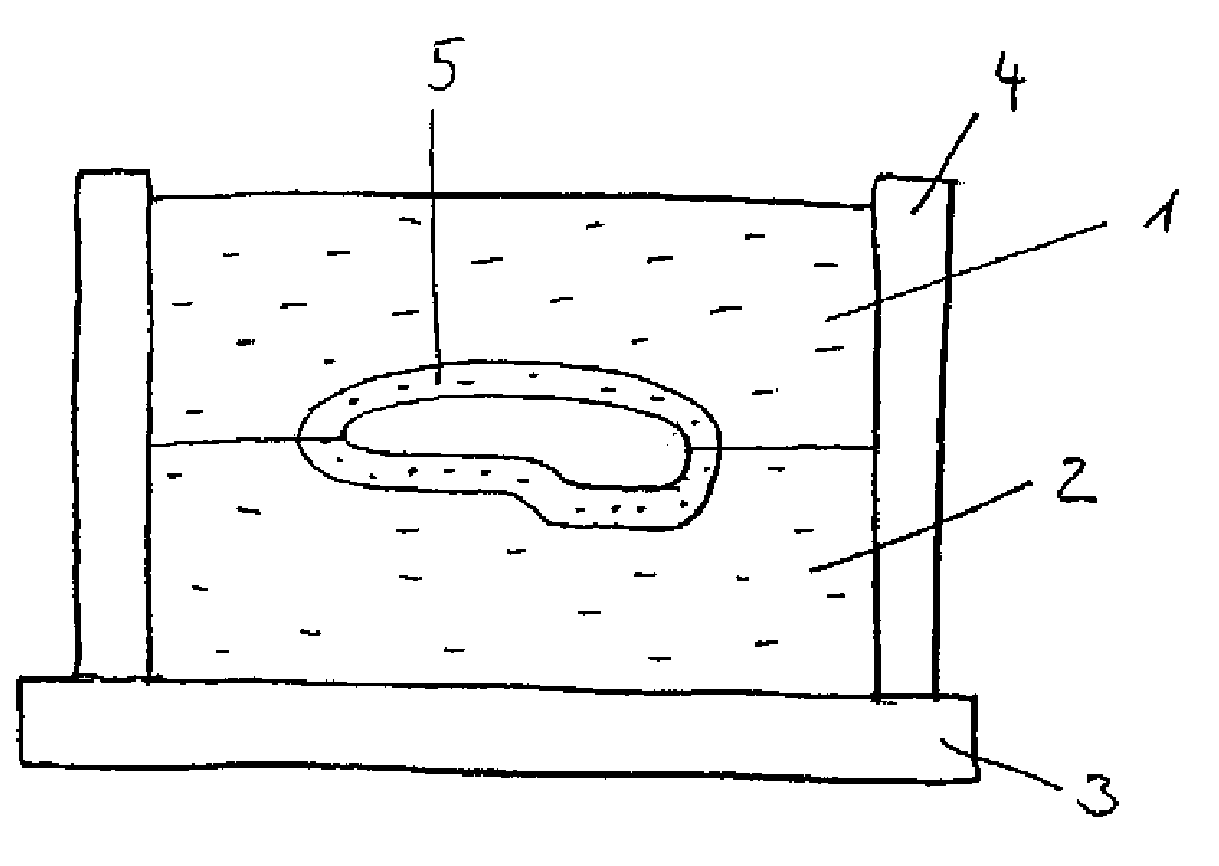
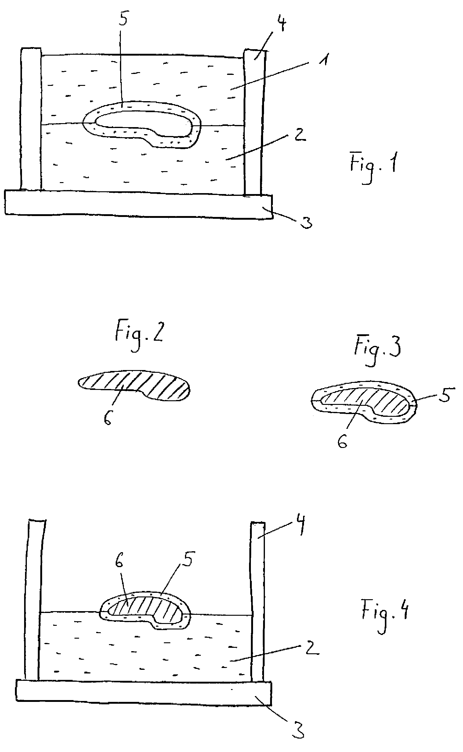
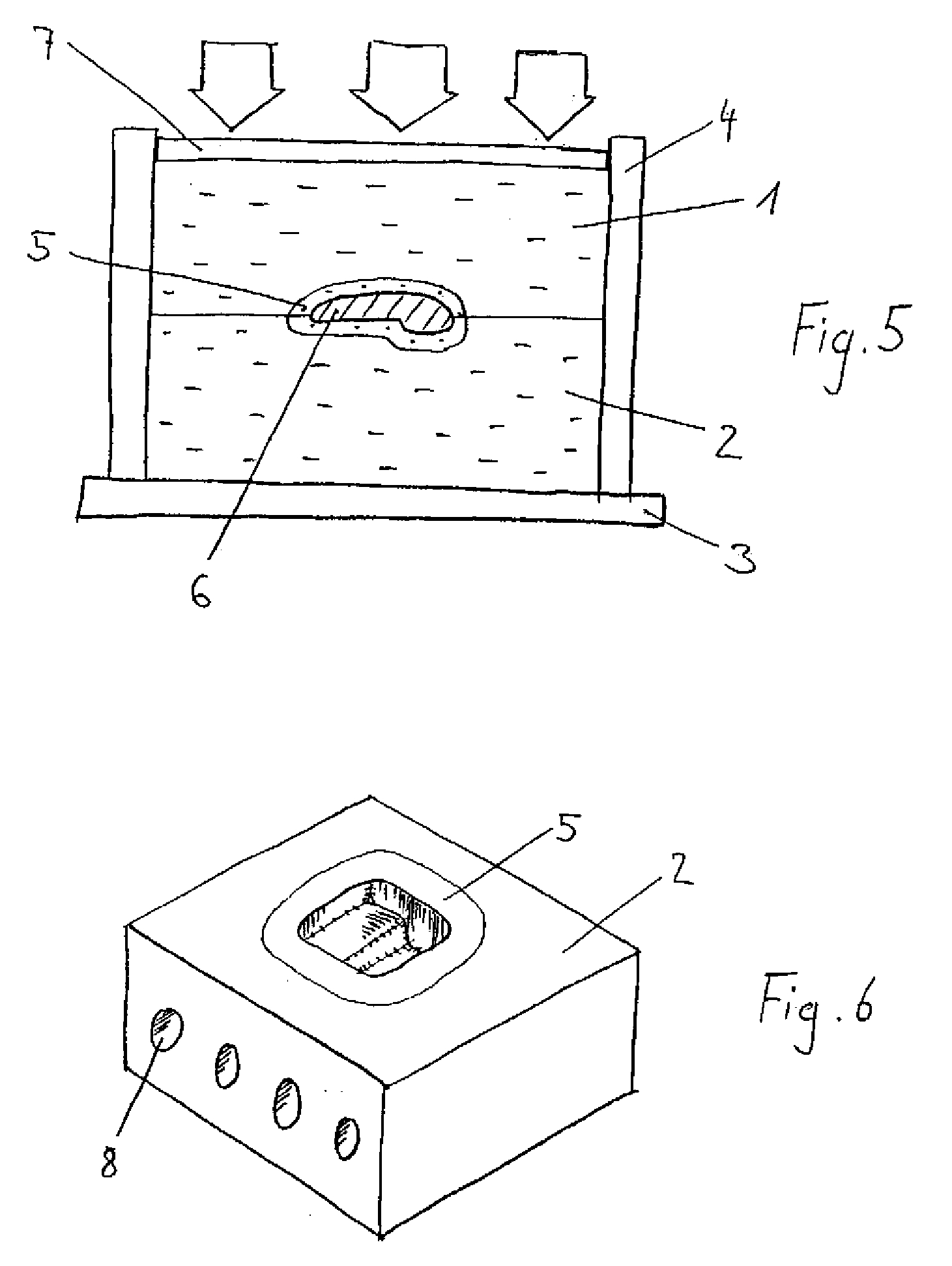
[0049] Turning now to the drawing, and in particular to FIG. 1, there is shown a schematic cross-sectional view of an assembled mold according to the present invention, including a top box 1 and a bottom box 2. Top box 1 and bottom box 2 are made up from a mold matrix material containing at least one type of carbon fibers and a phenolic resin. Close to the surface on which a ...


PUM

PropertyMeasurementUnit
flexural modulusaaaaaaaaaa
compressive modulusaaaaaaaaaa

Abstract

A mold for producing an article to be formed therein is provided wherein the mold matrix material contains at least one type of carbon fibers. The mold matrix material comprises a phenolic resin. Thereby, a high operating temperature of the mold matrix material and a wear resistant mold can be achieved. Hence, use of the mold in a series production becomes possible. Preferably, the mold matrix material comprises carbon nano fibers.

Description

CROSS-REFERENCES TO RELATED APPLICATIONS [0001] This application claims the priority of European Patent Applications, Serial No. 06450036.6, filed Mar. 14, 2006, and 06450152.1, filed Oct. 24, 2006, pursuant to 35 U.S.C. 119(a)-(d), the contents of which are incorporated herein by reference in its entirety as if fully set forth herein. BACKGROUND OF THE INVENTION [0002] The present invention relates to a mold for producing an article to be formed therein, the mold matrix material containing at least one type of carbon fibers. [0003] Nothing in the following discussion of the state of the art is to be construed as an admission of prior art. [0004] Steel molds are typically used for the manufacture of products in a series production. Due to minimal wear steel molds allow a high number of products to be molded within the same mold. However, steel molds cannot easily be changed in their design which makes them unfavorable during prototyping or the pre-production phase. Therefore, until ...

Claims


Application Information

Patent Timeline
Patent Type & Authority Applications(United States)
IPC IPC(8): B29C33/40B29C33/04
CPCB29C33/3857B29C33/40B29K2861/04B29K2707/04B29K2105/12
Inventor SHEPHEARD, PAUL
Owner ELECTROVAC
Why Eureka
Try Eureka