Extreme ultra violet light source apparatus

a light source and ultra violet technology, applied in the field of extreme ultra violet (euv) light source apparatus, can solve the problems of difficult mirrors, high cost of mirrors, and difficult apparatus, and achieve the effect of suppressing the production of debris

Active Publication Date: 2008-04-17
GIGAPHOTON
View PDF7 Cites 51 Cited by
  • Summary
  • Abstract
  • Description
  • Claims
  • Application Information

AI Technical Summary

Benefits of technology

[0021]According to the present invention, production of debris can be suppressed as much as possible by applying a laser beam having a relatively long wavelength generated by the CO2 laser to the target of solid tin or lithium.

Problems solved by technology

In the LPP EUV light source apparatus, the influence by neutral particles and ions emitted from plasma is problematic especially when a solid target is used.
In order to maintain the high reflectance, the high flatness of about 0.2 nm (rms), for example, is required for the EUV collector mirror, and thus, the mirror is very expensive.
However, when the mass of the target is restricted to the degree that no debris is produced at all, various technical problems may occur and the apparatus may be complicated.
However, since the debris shield is exposed to the plasma, the thin plates of the debris shield is worn away by fast ions and debris is produced, and the produced debris may be deposited on the reflecting surface of the EUV collector mirror.
However, the method of guiding debris by using a magnetic field or electric field is effective for ions, but not effective for neutral particles.
Therefore, the achievement of one-year mirror life is considered to be very difficult in an EUV light source apparatus for exposure having output of about 115 W to 180 W at the focusing point only by restricting the mass of the target or providing a debris shield.

Method used


Image

  • Extreme ultra violet light source apparatus
  • Extreme ultra violet light source apparatus
  • Extreme ultra violet light source apparatus

Examples


second embodiment

[0085]Next, the present invention will be explained.

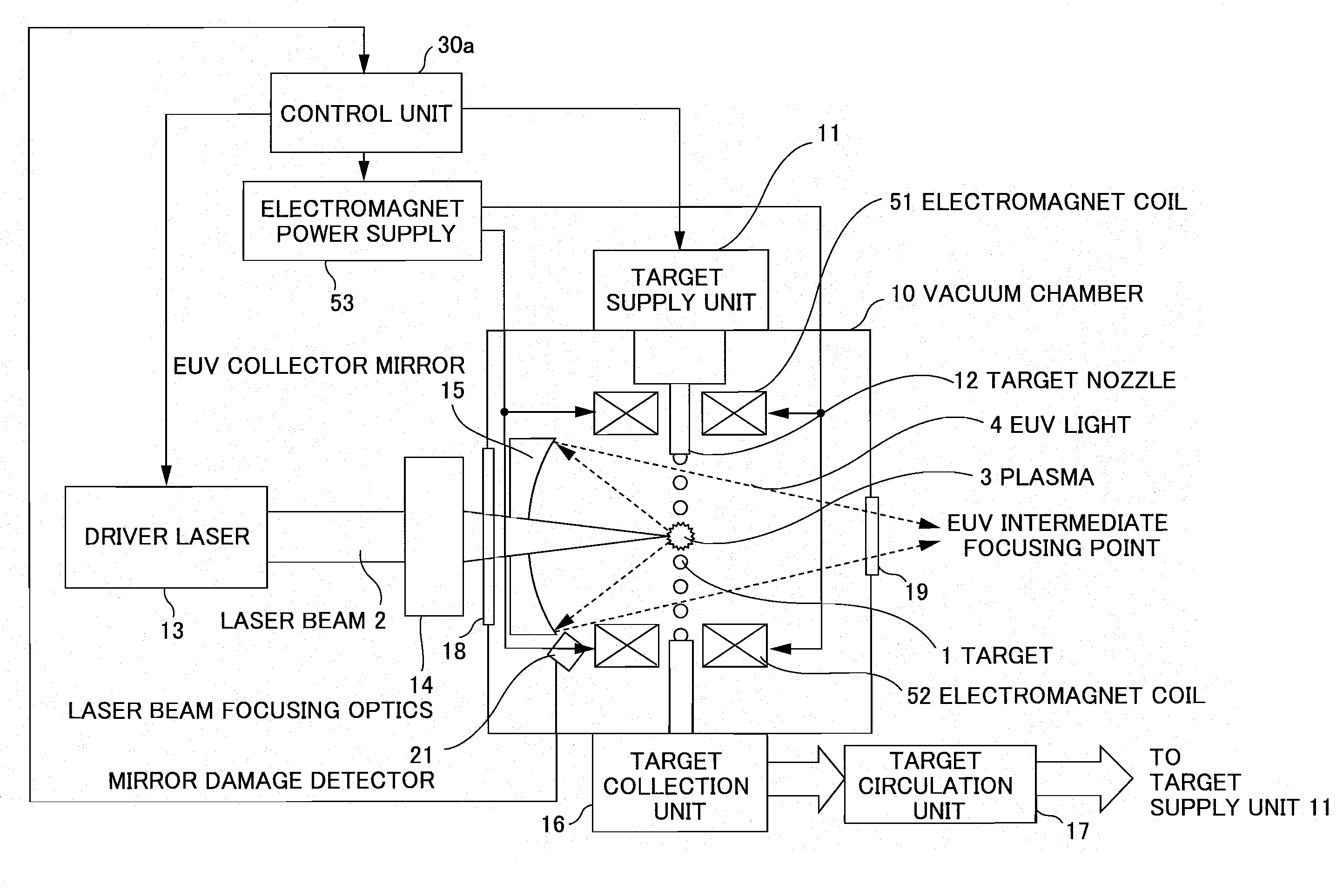
[0086]FIG. 15 shows a configuration of an EUV light source apparatus according to the second embodiment of the present invention. The EUV light source apparatus according to the embodiment further includes electromagnet coils 51 and 52 as a magnetic field generating unit for generating a magnetic field when applied with current, and an electromagnetic power supply 53 that supplies current to the electromagnet coils 51 and 52 in addition to the EUV light source apparatus shown in FIG. 13, and includes a control unit 30a that controls the entire EUV light source apparatus including the electromagnetic power supply 53 in place of the control unit 30.

[0087]FIG. 16 is a perspective view of the electromagnet coils shown in FIG. 15. As shown in FIG. 16, the electromagnet coils 51 and 52 respectively have cylindrical shapes and are located such that the central axes of the two coils are in line to form a pair of mirror coils. Further, the ...

third embodiment

[0097]Next, the present invention will be explained.

[0098]FIG. 19 is a perspective view of an electromagnet coil in an EUV light source apparatus according to the third embodiment of the present invention. The component elements other than the electromagnet coil are the same as those in the EUV light source apparatus according to the second embodiment of the present invention as shown in FIG. 15.

[0099]As shown in FIG. 19, the electromagnet coil 54 has a shape along the seams of a baseball, and generally called a baseball coil. The electromagnet coil 54 is provided so as to encompass the plasma 3 to be generated and wrap around the light emission point of EUV light, and thus, the light emission point of EUV light is located within the magnetic field. Especially, in the embodiment, the electromagnet coil 54 is provided such that the light emission point of EUV light is at the center of the ball shape. The baseball magnetic field generated by the electromagnet coil 54 traps positively ...


PUM


Abstract

An extreme ultra violet light source apparatus having relatively high output for exposure, in which debris are suppressed to be produced as much as possible in stead of disposing debris that has been once produced. The extreme ultra violet light source apparatus includes: a chamber in which extreme ultra violet light is generated; a target supply unit for supplying solid tin or lithium as a target to a predetermined position within the chamber; a CO2 laser for applying a laser beam based on pulse operation to the target supplied by the target supply unit so as to generate plasma; and a collector mirror having a multilayer film on a reflecting surface thereof, for collecting the extreme ultra violet light radiated from the plasma to output the extreme ultra violet light.

Description

BACKGROUND OF THE INVENTION[0001]1. Field of the Invention[0002]The present invention relates to an extreme ultra violet (EUV) light source apparatus to be used as a light source of exposure equipment.[0003]2. Description of a Related Art[0004]Recent years, photolithography has made rapid progress to finer fabrication with finer semiconductor processes. In the next generation, microfabrication of 100 nm to 70 nm, further, microfabrication of 50 nm or less will be required. Accordingly, in order to fulfill the requirement for microfabrication of 50 nm or less, for example, exposure equipment is expected to be developed by combining an EUV light source generating EUV light with a wavelength of about 13 nm and reduced projection reflective optics.[0005]The EUV light sources include three kinds, namely, an LPP (laser produced plasma) light source using plasma generated by applying a laser beam to a target, a DPP (discharge produced plasma) light source using plasma generated by electric...

Claims


Application Information

Patent Timeline
Patent Type & Authority Applications(United States)
IPC IPC(8): H05G2/00
CPCB82Y10/00H05G2/001G03F7/70033
Inventor UENO, YOSHIFUMISOUMAGNE, GEORGSUMITANI, AKIRAWAKABAYASHI, OSAMU
Owner GIGAPHOTON
Why Eureka
Try Eureka