Nitride semiconductor device and method for fabricating the same
a technology of semiconductor devices and semiconductors, applied in the field of nitride semiconductor transistors, can solve the problems of difficult to exhibit enhancement (normally off) characteristics, high sheet carrier densities at the interface, and high cost, and achieve the effect of fast switching operation and large operating curren
- Summary
- Abstract
- Description
- Claims
- Application Information
AI Technical Summary
Benefits of technology
Problems solved by technology
Method used
Image
Examples
first embodiment
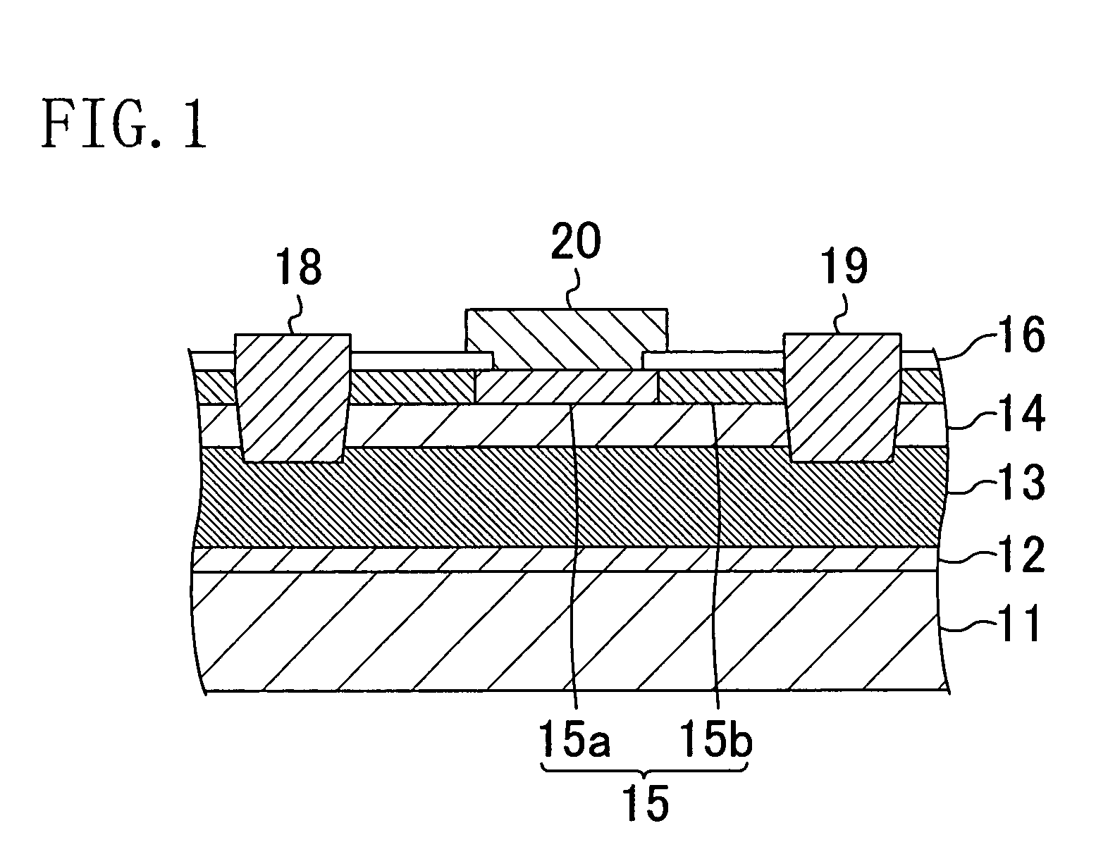
[0030]A first embodiment of the present invention will be described with reference to the accompanying drawings. FIG. 1 shows a cross-sectional structure of a nitride semiconductor transistor according to the first embodiment of the present invention.
[0031]Referring to FIG. 1, a substrate 11 is made of silicon and its principal plane is the (111) plane. A buffer layer 12 of AlN having a thickness of 100 nm is formed on the principal plane of the substrate 11.
[0032]A first nitride semiconductor layer 13 of undoped GaN having a thickness of 2 μm and a second nitride semiconductor layer 14 of undoped Al0.15Ga0.85N having a thickness of 25 nm are formed on the buffer layer 12. A channel region of the transistor which will be described later is formed in the interface region between the first nitride semiconductor layer 13 and the second nitride semiconductor layer 14.
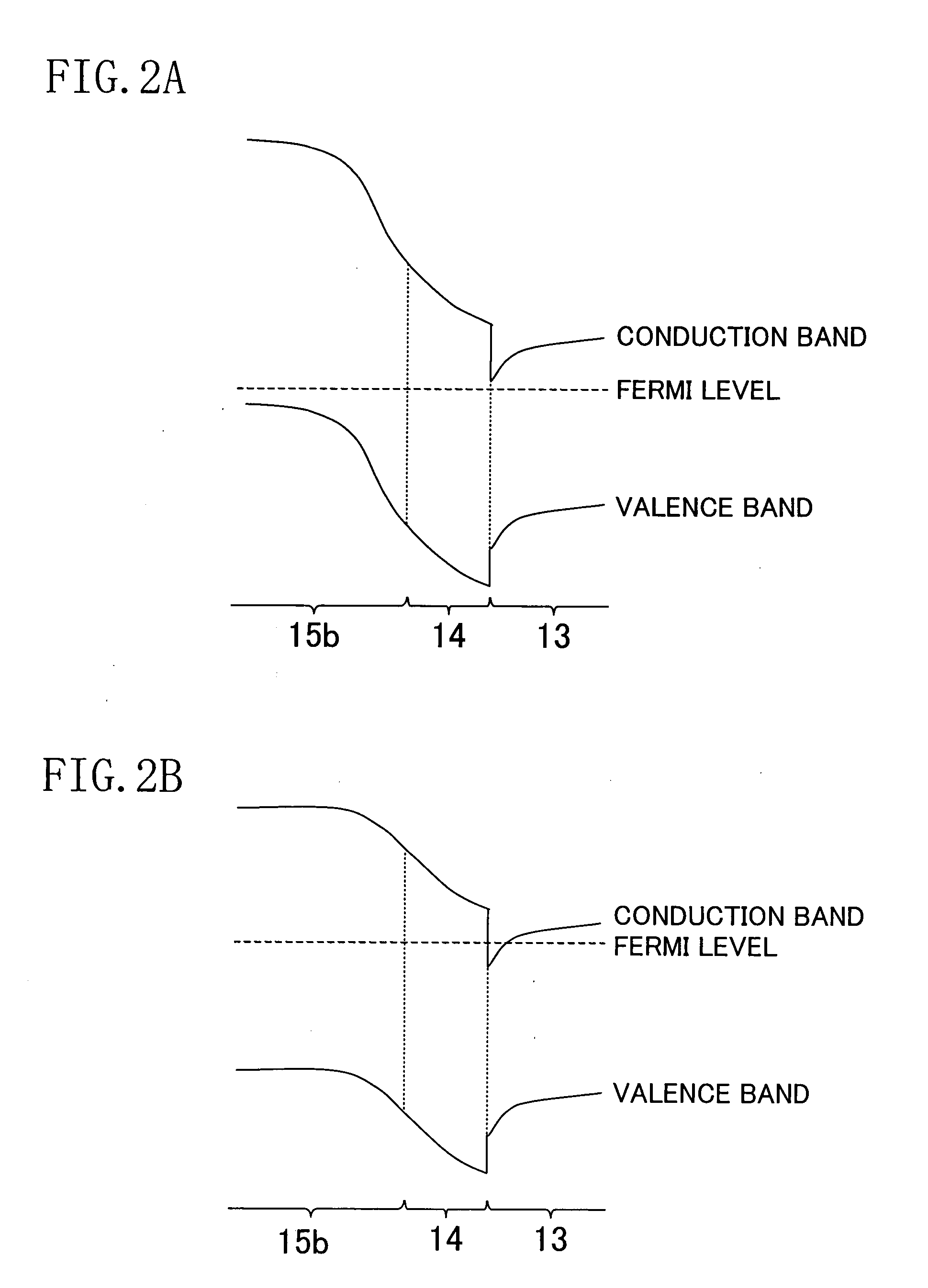
[0033]On the second nitride semiconductor layer 14, a third nitride semiconductor layer 15 is formed which is made of Al0...
second embodiment
[0057]A second embodiment of the present invention will be described below with reference to the accompanying drawings. FIG. 5 shows a cross-sectional structure of a nitride semiconductor transistor according to the second embodiment. The description of the components shown in FIG. 5 that are the same as those shown in FIG. 1 will be omitted by retaining the same reference numerals.
[0058]Referring to FIG. 5, the transistor according to the second embodiment has a thin portion formed in a portion of the high resistive region 15b located between the control region 15a and each of the drain electrode 19 and the source electrode 18.
[0059]As the resistance of the high resistive region 15b between the control region 15a and the drain electrode 19 is higher, a greater amount of leakage current between the gate and the drain can be reduced. The resistance of the high resistive region 15b increases with a decreasing thickness. Therefore, in the transistor of the second embodiment, the high r...
third embodiment
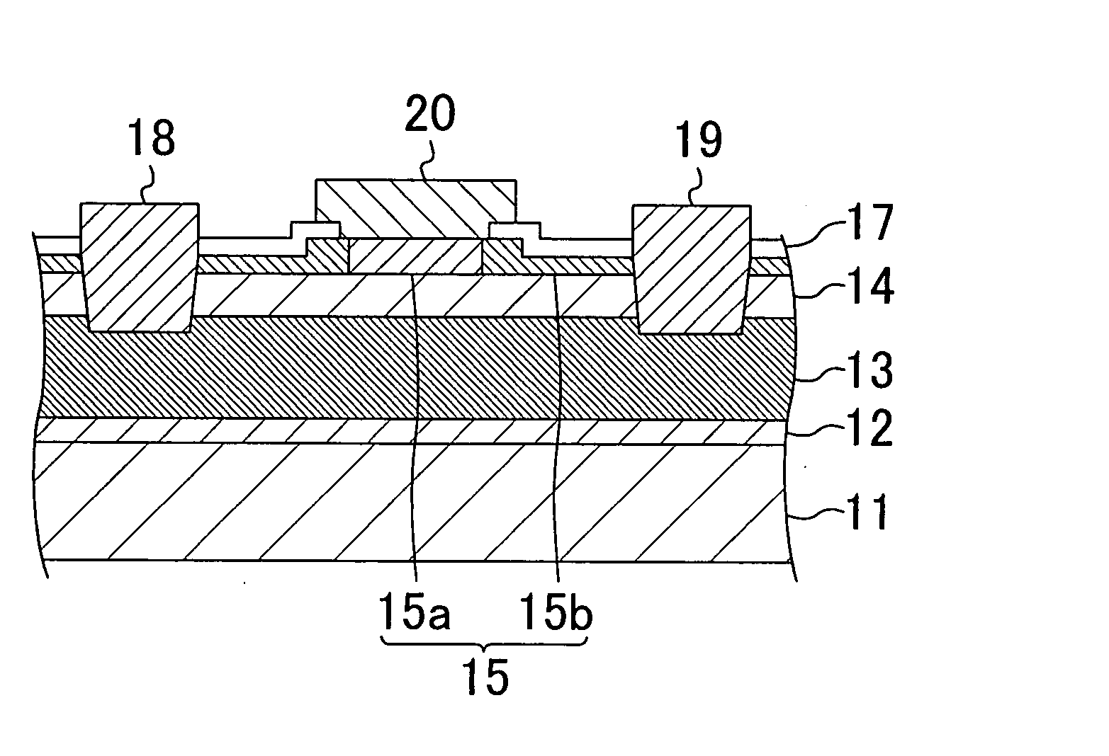
[0062]A third embodiment of the present invention will be described below with reference to the accompanying drawings. FIG. 7 shows a cross-sectional structure of a nitride semiconductor transistor according to the third embodiment. The description of the components shown in FIG. 7 that are the same as those shown in FIG. 5 will be omitted by retaining the same reference numerals.
[0063]Referring to FIG. 7, in the transistor according to the third embodiment, the top of the third nitride semiconductor layer 15 is formed with not a hydrogen diffusion barrier film but a hydrogen diffusion film 17 for supplying hydrogen. It is sufficient that the hydrogen diffusion film 17 is deposited by, for example, a plasma enhanced CVD method and made of silicon nitride (SiN) containing equal to or more than 1×10²⁰ / cm3 of hydrogen. The SiN film containing hydrogen releases hydrogen by a thermal treatment. Therefore, to a portion of the third nitride semiconductor layer 15 covered with the hydrogen ...
PUM
 Abstract
Description
Claims
Application Information
 - R&D
- Intellectual Property
- Life Sciences
- Materials
- Tech Scout
- Unparalleled Data Quality
- Higher Quality Content
- 60% Fewer Hallucinations
Browse by: Latest US Patents, China's latest patents, Technical Efficacy Thesaurus, Application Domain, Technology Topic, Popular Technical Reports.
© 2025 PatSnap. All rights reserved.Legal|Privacy policy|Modern Slavery Act Transparency Statement|Sitemap|About US| Contact US: help@patsnap.com


