Multi-Mode Tags and Methods of Making and Using the Same

a technology of radio frequency identification and multi-mode tags, which is applied in the field of electronic article surveillance and/or radio frequency identification tags, can solve the problems of insufficient storage of information for inventory control and insufficient operation range of rfid tags for anti-theft use, and achieve the effect of simplifying product and inventory management and reducing the cost of performing

Inactive Publication Date: 2008-04-17
ENSURGE MICROPOWER ASA
View PDF32 Cites 51 Cited by
  • Summary
  • Abstract
  • Description
  • Claims
  • Application Information

AI Technical Summary

Benefits of technology

[0016]The present invention advantageously provides a tag that provides both an EAS function and a RFID function. Thus, the tag is useful as an RFID tag, both before and after the EAS function is disabled. As a result, manufacturers, wholesalers, distributors and retailers can use a single tag for RF and EAS functions, thereby simplifying product and inventory management and potentially reducing the costs of performing and / or providing both functions.

Problems solved by technology

As is known in the art, EAS tags are useful for anti-theft detection, but generally do not store enough information for inventory control.
On the other hand, RFID tags typically do not have an operational range sufficient for anti-theft uses, since they typically need to be within a short distance of the reader to obtain sufficient power to operate.

Method used


Image

  • Multi-Mode Tags and Methods of Making and Using the Same
  • Multi-Mode Tags and Methods of Making and Using the Same
  • Multi-Mode Tags and Methods of Making and Using the Same

Examples


third embodiment

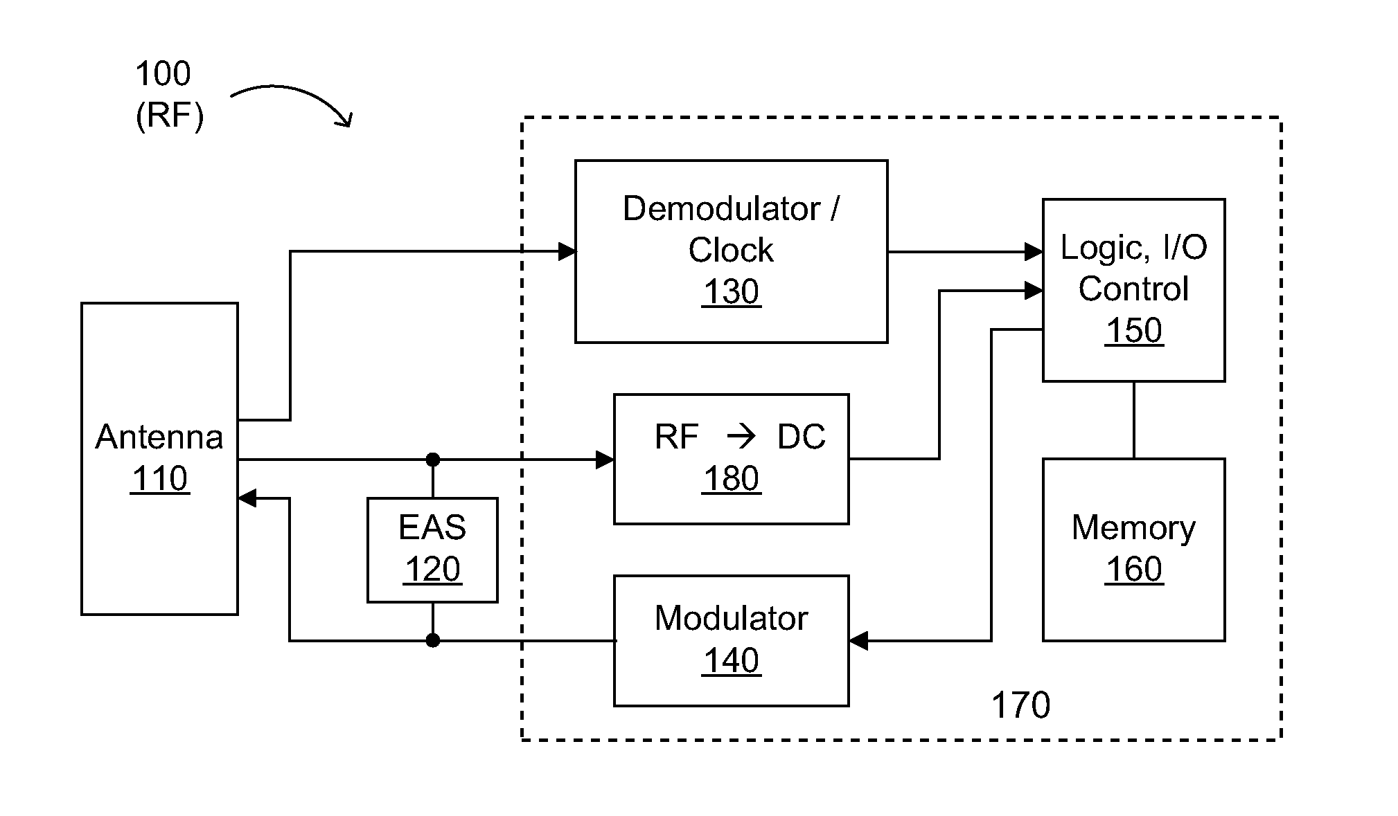
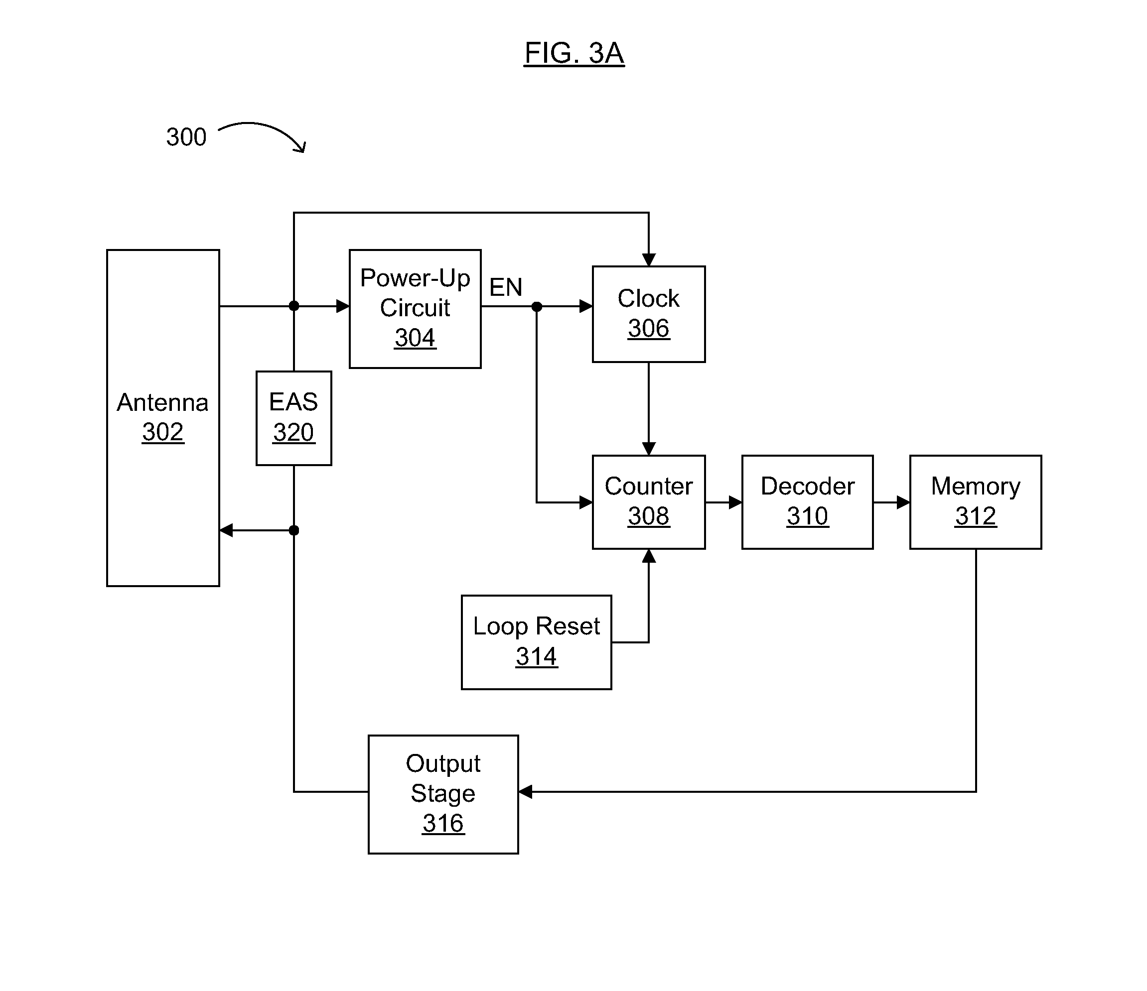
[0083]In general, an RFID portion of the dual-mode tag 300 can include an antenna section (e.g., 302), a power-up circuit (e.g., 304), a clock subcircuit (e.g., 306), a counter (e.g., 308), a memory portion (e.g., 312), a decoder (e.g., 310), a loop reset circuit (e.g., 314), and an output stage (e.g., 316). Portions of or all such circuit portions (except, in some embodiments, the antenna 302) can be printable in order to reduce overall system costs.

[0084]The antenna 302 may be implemented using a resonant LC circuit for use at 13.56 MHz, for example, but tunable for use at, e.g.,.8.2 MHz (i.e., at a frequency typical of EAS applications). Alternatively, the antenna may be implemented using a dipole or similar such antenna for 900 MHz (high frequency, or HF) operation or 2.4 GHz (very high frequency, or VHF) operation. Generally, the antenna may be used to provide power for operation of the tag circuitry, and to provide information from the tag to the reader or interrogator. Using ...

working example

[0102

[0103]An existing 13 MHz tag, connected to an antenna tuned to 8 MHz, can function as an RFID tag close to a reader and as an EAS tag at a distance from the reader, as demonstrated by simulation as well as by measurements taken on RFID tag circuitry designed for operation at 13.56 MHz, but tested at 8 MHz. A rectifier circuit with a voltage-controlled turn-on has been designed (see, e.g., U.S. patent application Ser. No. 11 / 521,924) and fabricated using Si ink technology (see, e.g., U.S. patent application Ser. Nos. 10 / 789,317, 10 / 949,013, 10 / 950,373, and 10 / 956,714, filed on Feb. 27, 2004, Sep. 24, 2004, Sep. 24, 2004, and Oct. 1, 2004 respectively [Attorney Docket Nos. IDR0020, IDR0301, IDR0302, and / or IDR0303]) and an externally attached capacitor. The rectifier circuit is configured to prevent the RFID circuitry from affecting the EAS operation at a distance. The 8.2 MHz EAS mode antenna resonated strongly enough to be detected by a commercially available EAS reader (from C...


PUM


Abstract

Multi-mode (e.g., EAS and RFID) tags and methods for making and using the same are disclosed. The tag generally includes an antenna, an electronic article surveillance (EAS) function block coupled to the antenna, and one or more identification function blocks coupled to the antenna in parallel with the EAS function block. The method of reading the tag generally includes the steps of applying an electric field to the tag, detecting the tag when the electric field has a relatively low power, and detecting an identification signal from the tag when the electric field has a relatively high power. The present invention advantageously enables a single tag to be used for both inventory and anti-theft purposes, thereby improving inventory management and control at reduced system and/or “per-article” costs.

Description

RELATED APPLICATIONS[0001]This application claims the benefit of U.S. Provisional Application No. 60 / 851,122, filed Oct. 11, 2006 (Attorney Docket No. IDR1001), and U.S. Provisional Application No. 60 / 880,827, filed Jan. 16, 2007 (Attorney Docket No. IDR1005), both of which are incorporated herein by reference in their entireties.FIELD OF THE INVENTION[0002]The present invention generally relates to EAS (electronic article surveillance) and / or RFID (radio frequency identification) tags. More specifically, embodiments of the present invention pertain to multi-mode (e.g., “dual use” tags, having EAS and RFID functions thereon, for example) tags and methods for making and using the same.DISCUSSION OF THE BACKGROUND[0003]As is known in the art, EAS tags are useful for anti-theft detection, but generally do not store enough information for inventory control. On the other hand, RFID tags typically do not have an operational range sufficient for anti-theft uses, since they typically need t...

Claims


Application Information

Patent Timeline
Patent Type & Authority Applications(United States)
IPC IPC(8): H04B7/00G08B13/14A47J37/04A47J37/07A47J43/18
CPCG06K19/0707G06K19/0712H04W88/06G08B13/2448G06K19/0723Y02D30/70
Inventor SMITH, PATRICKCLEEVES, JAMES MONTAGUEPAVATE, VIKRAMSUBRAMANIAN, VIVEK
Owner ENSURGE MICROPOWER ASA
Why Eureka
Try Eureka