
System and Method for Incubating the Contents of A Reaction Receptacle

a technology of reaction receptacle and reaction receptacle, which is applied in the field of automatic analyzer, can solve the problems of practitioner error, cross-contamination between assays, and exposure to pathogens, and achieve the effects of efficient space utilization, high through-put operation of the analyzer, and efficient use of spa

Inactive Publication Date: 2008-04-17
GEN PROBE INC
View PDF114 Cites 19 Cited by
  • Summary
  • Abstract
  • Description
  • Claims
  • Application Information

AI Technical Summary

Benefits of technology

The automated system significantly reduces user-error, pathogen exposure, and contamination risks while increasing throughput, reducing training requirements and minimizing physical hazards, and enabling efficient high-volume nucleic acid-based assay processing.

Problems solved by technology

When performed manually, the complexity and shear number of processing steps associated with a nucleic acid-based assay introduce opportunities for practitioner-error, exposure to pathogens, and cross-contamination between assays.
Although applying a magnetic field to only one side of the assay receptacle is a less efficient means for performing a target capture assay, it is designed to prevent magnetic particles from being unnecessarily aspirated as a result of practitioner inaccuracies.

Method used


Image

  • System and Method for Incubating the Contents of A Reaction Receptacle
  • System and Method for Incubating the Contents of A Reaction Receptacle
  • System and Method for Incubating the Contents of A Reaction Receptacle

Examples


Embodiment Construction

Analyzer Overview

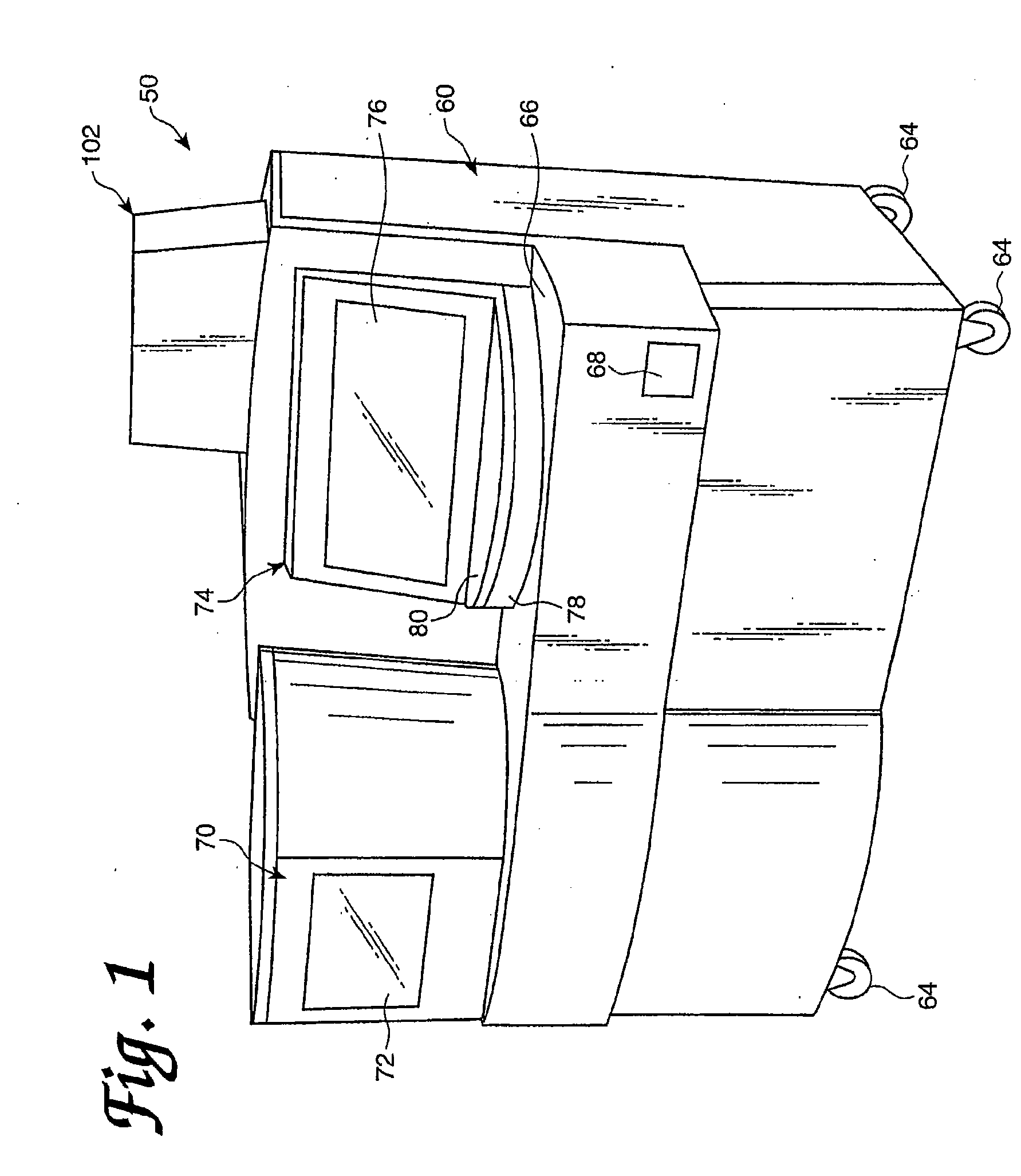
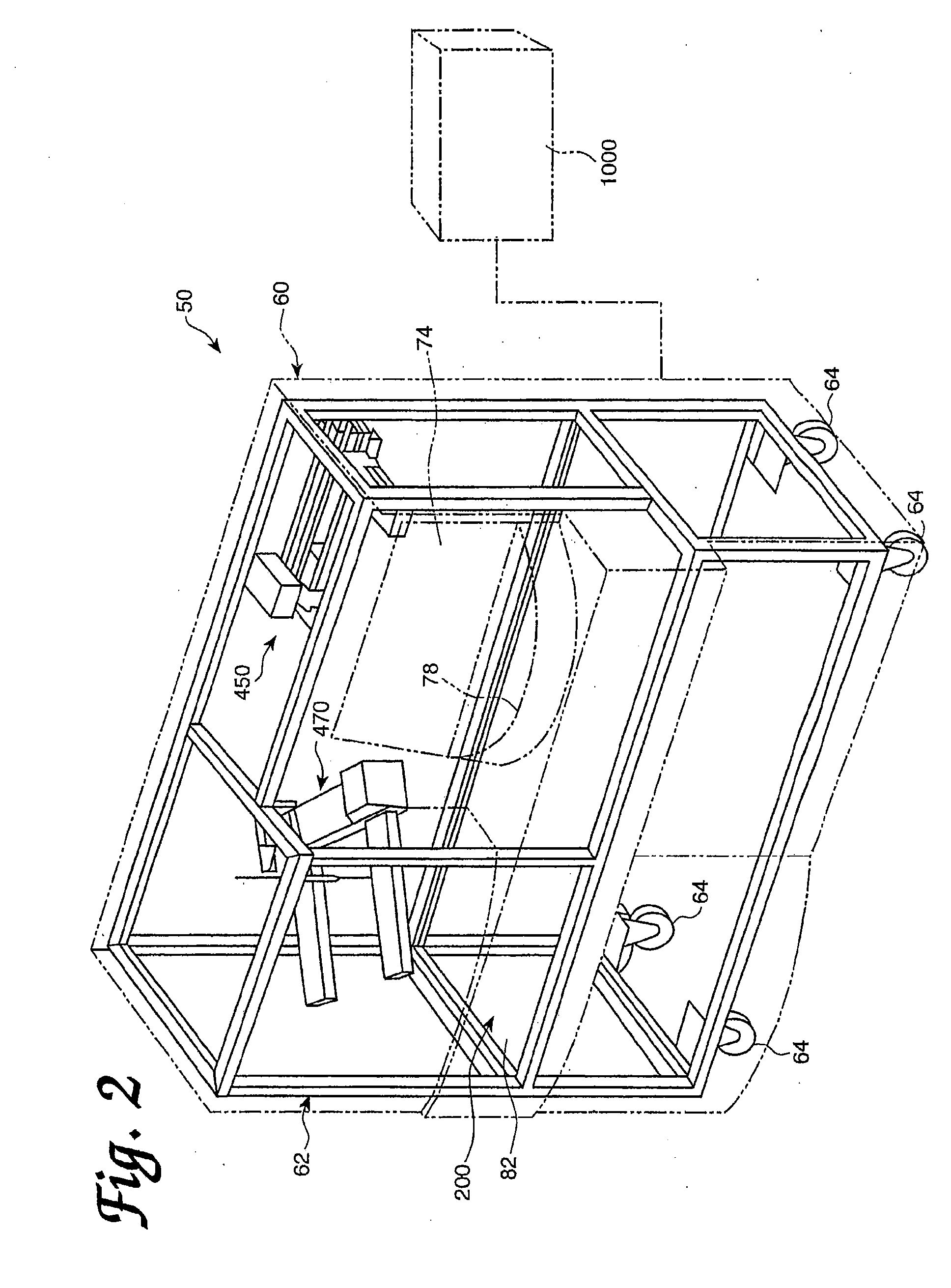
[0093] An automated diagnostic analyzer according to the present invention is designated generally by reference number 50 in FIGS. 1 and 2. Analyzer 50 includes a housing 60 built over an internal frame structure 62, preferably made of steel. The analyzer 50 is preferably supported on caster wheels 64 structurally mounted to the frame structure 62 so as to make the analyzer movable.

[0094] The various stations involved in performing an automated assay and the assay specimens are housed within housing 60. In addition, the various solutions, reagents, and other materials used in performing the assays are preferably stored within the housing 60, as are the waste products generated when assays are performed with the analyzer 50.

[0095] Housing 60 includes a test receptacle loading opening 68, which is shown in FIG. 1 to be disposed in a forwardly facing panel of the housing 60, but could as well be located in other panels of the housing 60. A pipette door 70 having a v...


PUM

PropertyMeasurementUnit
temperatureaaaaaaaaaa
distanceaaaaaaaaaa

Abstract

An automated analyzer for performing multiple diagnostic assays simultaneously includes multiple stations, or modules, in which discrete aspects of the assay are performed on fluid samples contained in reaction receptacles. The analyzer includes stations for automatically preparing a specimen sample, incubating the sample at prescribed temperatures for prescribed periods, performing an analyte isolation procedure, and ascertaining the presence of a target analyte. An automated receptacle transporting system moves the reaction receptacles from one station to the next. The analyzer further includes devices for carrying a plurality of specimen tubes and disposable pipette tips in a machine-accessible manner, a device for agitating containers of target capture reagents comprising suspensions of solid support material and for presenting the containers for machine access thereto, and a device for holding containers of reagents in a temperature controlled environment and presenting the containers for machine access thereto. A method for performing an automated diagnostic assay includes an automated process for isolating and amplifying a target analyte. The process is performed by automatically moving each of a plurality of reaction receptacles containing a solid support material and a fluid sample between stations for incubating the contents of the reaction receptacle and for separating the target analyte bound to the solid support from the fluid sample. An amplification reagent is added to the separated analyte after the analyte separation step and before a final incubation step.

Description

CROSS-REFERENCE TO RELATED APPLICATIONS [0001] This application is a continuation of U.S. application Ser. No. 11 / 772,453, filed Jul. 2, 2007, which is a continuation of U.S. application Ser. No. 10 / 073,346, filed Feb. 13, 2002, now U.S. Pat. No. 7,267,795, which is a continuation of U.S. application Ser. No. 09 / 985,064, filed Nov. 1, 2001, now U.S. Pat. No. 6,890,742, which is a continuation of U.S. application Ser. No. 09 / 303,030, filed Apr. 30, 1999, now U.S. Pat. No. 6,335,166, which claims the benefit of U.S. Provisional Application No. 60 / 083,927, filed May 1, 1998, the disclosures of which are hereby incorporated by reference herein.1. FIELD OF THE INVENTION [0002] The present invention relates to an automated analyzer for performing multiple diagnostic assays simultaneously. 2. BACKGROUND OF THE INVENTION [0003] None of the references described or referred to herein are admitted to be prior art to the claimed invention. [0004] Diagnostic assays are widely used in clinical di...

Claims


Application Information

Patent Timeline
Patent Type & Authority Applications(United States)
IPC IPC(8): B01J19/00C12M1/38B01L7/00G01N35/00G01N35/04G01N35/10
CPCB01L7/52Y10T436/119163B01L2200/147B01L2300/1822B01L2300/1827G01N35/0098G01N35/0099G01N2035/00356G01N2035/00524G01N2035/0437G01N2035/0455G01N2035/103Y10T436/115831Y10T436/11Y10T436/113332Y10T436/2575Y10T436/25B01L7/5255
Inventor AMMANN, KELLY G.SCHNEIDER, ROBERT E.SMITH, ROBERT J.
Owner GEN PROBE INC
Learn More