
Method of manufacturing laminated glass for vehicle and laminated glass for vehicle

a technology of laminated glass and vehicle, which is applied in the field of manufacturing a laminated glass and a vehicle, can solve problems such as not necessarily the case, and achieve the effects of reducing preventing the difference in bend degree, and reducing the gap between edges

Active Publication Date: 2008-04-24
NIPPON SHEET GLASS CO LTD
View PDF7 Cites 10 Cited by
  • Summary
  • Abstract
  • Description
  • Claims
  • Application Information

AI Technical Summary

Benefits of technology

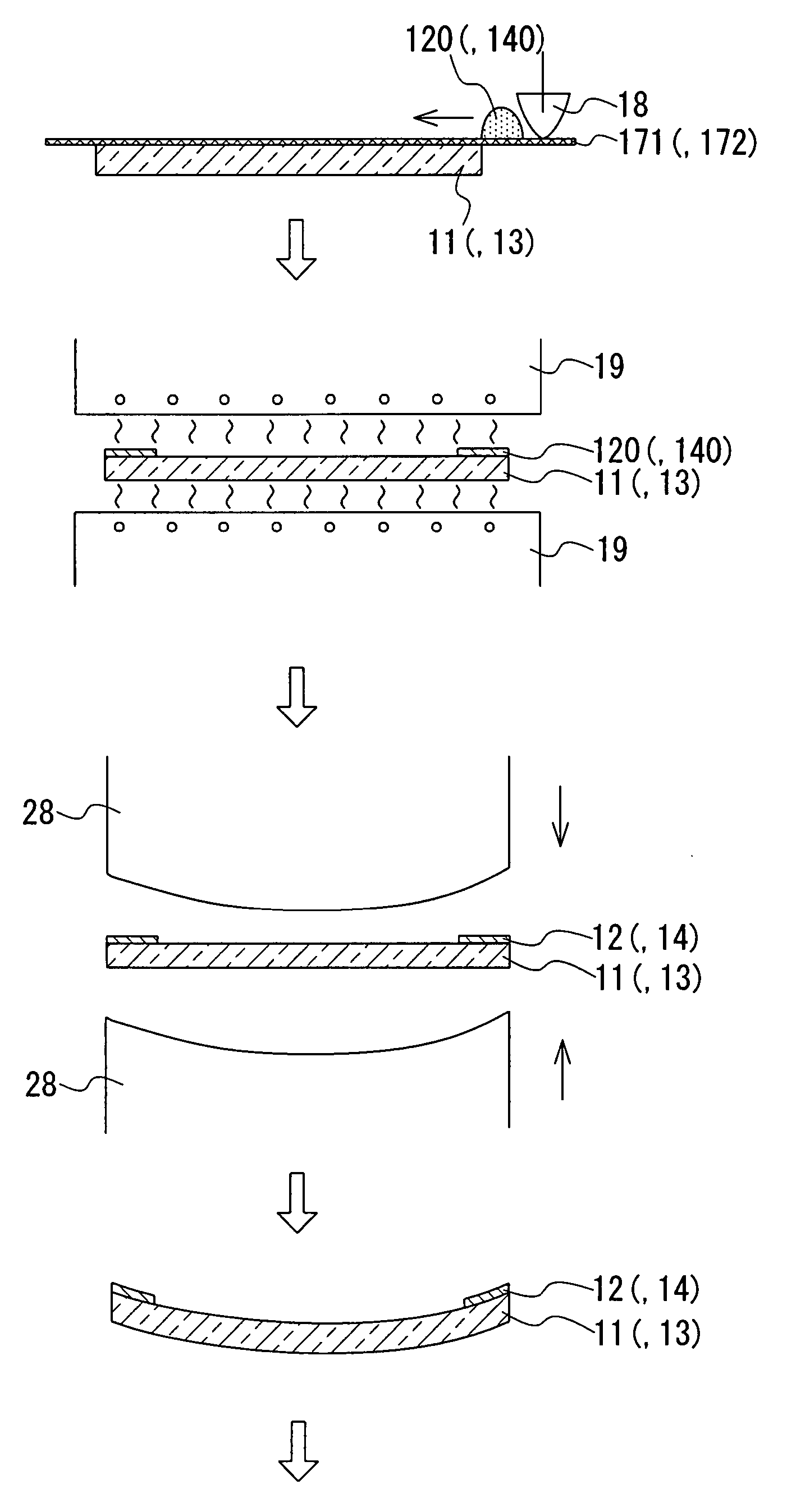
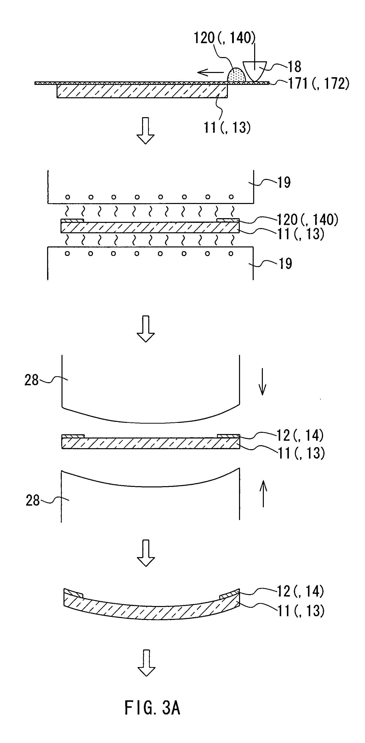
[0013] wherein in the processes (A1) and (A2), in order to reduce the difference in bend degree between the peripheral parts of the first glass sheet and the second glass sheet, which is caused by firing shrinkages of the first ceramic paste and the second ceramic paste in the process (B),
[0023] This allows the difference in thermal characteristics between the first glass sheet and the second glass sheet to be cancelled out by the difference in effects of firing shrinkage of the ceramic pastes. Accordingly, it is possible to prevent the difference in bend degree between the peripheral parts of the first glass sheet and the second glass sheet from becoming excessively large. The edge gap can be reduced considerably by reducing the difference in bend degree between the peripheral parts of the first glass sheet and the second glass sheet as much as possible, preferably by allowing the bend degrees thereof to coincide with each other. As a result, the first glass sheet and the second glass sheet can be bonded reliably to each other without applying excessively high pressure or using a special resin interlayer film.

Problems solved by technology

However, that is not necessarily the case.

Method used


Image

  • Method of manufacturing laminated glass for vehicle and laminated glass for vehicle
  • Method of manufacturing laminated glass for vehicle and laminated glass for vehicle
  • Method of manufacturing laminated glass for vehicle and laminated glass for vehicle

Examples


examples

[0077] A clear glass sheet with a thickness of 2.1 mm (FL, manufactured by Nippon Sheet Glass, Co., Ltd.) to be used as a first glass sheet and a heat absorbing glass sheet with a thickness of 2.1 mm (MFL, manufactured by Nippon Sheet Glass, Co., Ltd.) to be used as a second glass sheet each were produced by a known float glass process. The compositions of the respective glass sheets were adjusted so that the second glass sheet (outer sheet) had a lower solar transmittance than that of the first glass sheet (inner sheet).

[0078] With respect to these glass sheets, the visible-light transmittance (in a wavelength region of 380 to 780 nm), solar transmittance (in a wavelength region of 300 to 2500 nm), and infrared transmittance (at a wavelength of 1550 nm) were measured by using a spectrophotometer according to Japanese Industrial Standards (JIS) R3212:1998 and R3106:1998.

[0079] The clear glass sheet had a visible-light transmittance of 90.7%, a solar transmittance of 88.4%, and an ...


PUM

PropertyMeasurementUnit
Thicknessaaaaaaaaaa
Compositionaaaaaaaaaa
Areaaaaaaaaaaa

Abstract

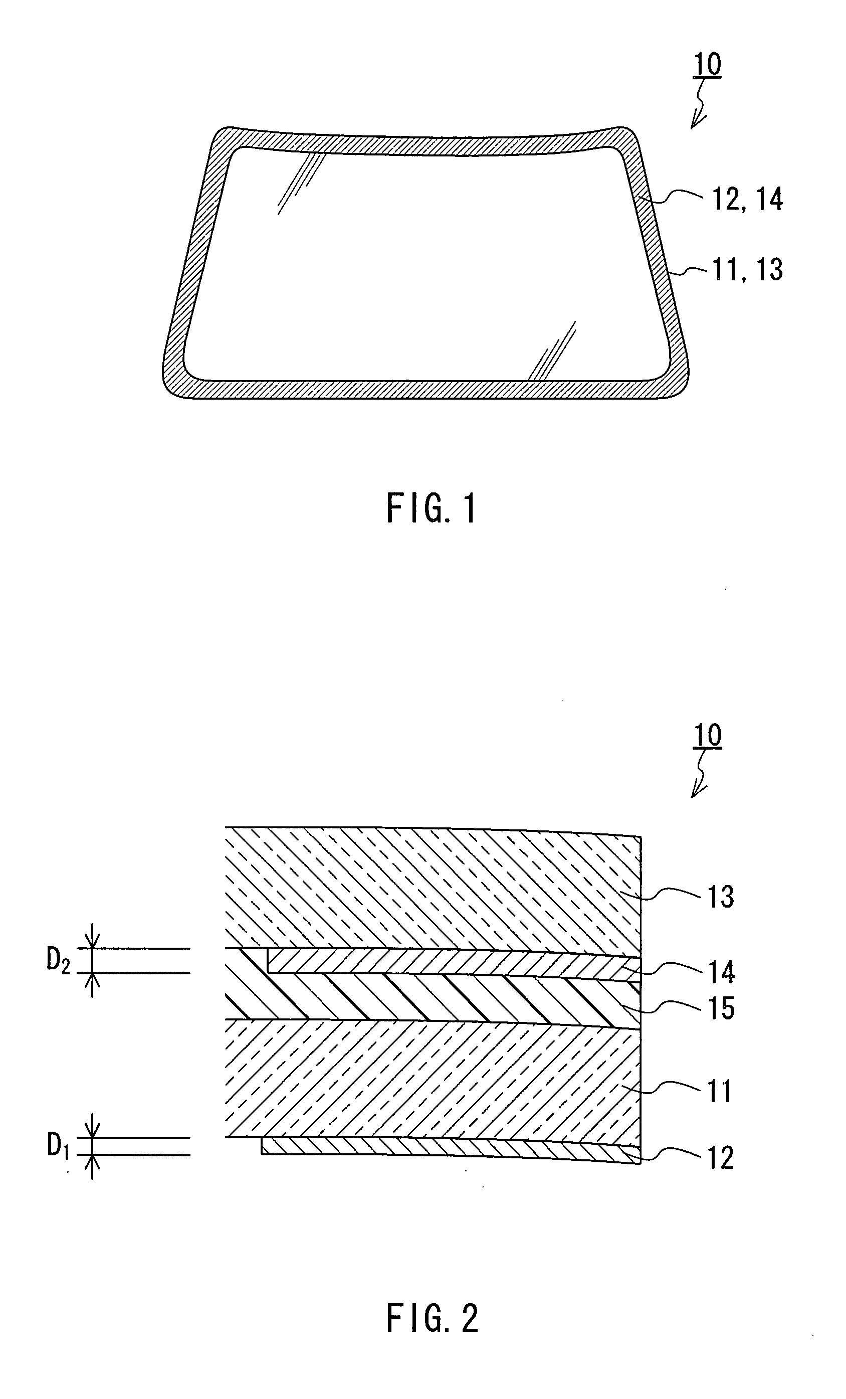
A ceramic paste is applied to a first glass sheet 11, and a ceramic paste is applied to a second glass sheet 13 with a lower solar absorptivity than that of the first glass sheet 11. In this case, the amount per unit area of the ceramic paste to be applied to the first glass sheet 11 is allowed to be smaller than that of the ceramic paste to be applied to the second glass sheet 13. Alternatively, a first ceramic paste and a second ceramic paste are allowed to have different compositions from each other. The first glass sheet 11 and the second glass sheet 13 are bent so that the surfaces onto which the ceramic pastes have been applied are shaped as concave surfaces. The applied ceramic paste is fired using the heating used for bending. Thus maskings 12 and 14 are formed. The first glass sheet 11 and the second glass sheet 13 are bonded to each other, with a resin interlayer film 15 being interposed therebetween.

Description

BACKGROUND OF THE INVENTION [0001] 1. Field of the Invention [0002] The present invention relates to a method of manufacturing a laminated glass for vehicles, and a laminated glass for vehicles. [0003] 2. Related Background Art [0004] For window glasses of automobiles, laminated glasses are used, each of which is formed of two glass sheets bonded to each other with a resin interlayer film interposed therebetween and dark-colored maskings provided for the peripheral parts thereof in the form of a frame (for instance, JP 2005-213101 A, JP2005-29083 A). The maskings are referred to often as “ceramic prints”. The maskings are intended to prevent an adhesive for fixing a window glass to a window frame from deteriorating due to solar radiation and to improve the appearance by shielding terminals of heating wires or a deicer. [0005] The maskings each are formed by printing a ceramic paste on peripheral parts of glass sheets to be bonded to each other and firing the ceramic paste that has b...

Claims


Application Information

Patent Timeline
IPC IPC(8): B32B17/06B32B37/14
CPCB32B17/10036B32B17/10761B32B17/10889C03B23/025C03B23/0302Y10T428/24926C03C2218/34Y10S428/913Y10T156/1028Y10T156/10Y10T428/24802C03C17/04Y02P40/57B32B17/10348
Inventor YAMADA, KAZUONISHIMOTO, SHINICHISHIMOMURA, TAKAHIRO
Owner NIPPON SHEET GLASS CO LTD
Learn More