
System implementing low-reductant engine operation mode

a low-reductance, engine-based technology, applied in the direction of machines/engines, electric control, instruments, etc., can solve the problems of inconvenient stranding of vehicles, costing the owner of vehicles considerable time and resources, and still be problemati

Active Publication Date: 2008-05-01
CATERPILLAR INC
View PDF14 Cites 33 Cited by
  • Summary
  • Abstract
  • Description
  • Claims
  • Application Information

AI Technical Summary

Benefits of technology

[0047]Another advantage of the present disclosure is that it provides a strategy for dealing with a sufficient supply of reductant that is simply unavailable at a required rate, such as when the reductant is frozen and melting slowly. This allows operation to continue at a low-reductant and high-fuel use mode where previous systems would require a period in which all operation was prohibited to allow a sufficient supply of reductant to melt.

Problems solved by technology

Another such guideline may require limited utility, including the possibility that an engine without an adequate supply of urea would have a limited number of restarts While these guideline may adequately prevent excessive amounts of NOx from being expelled to the environment, they may be problematic.
For example, a vehicle could become inconveniently stranded, costing the owner of the vehicle considerable time and resources.
Although the travel assist system of the '307 publication may suitably enable a vehicle to reach a service station without running completely out of the aqueous urea solution, it may still be problematic.
In this situation, the vehicle would no longer be compliant with emission regulations.
In addition, the system of the '307 patent does not provide a strategy for dealing with a sufficient supply of urea that is simply unavailable at a required rate, such as when the urea supply is frozen and melting slowly.

Method used


Image

  • System implementing low-reductant engine operation mode
  • System implementing low-reductant engine operation mode
  • System implementing low-reductant engine operation mode

Examples


Embodiment Construction

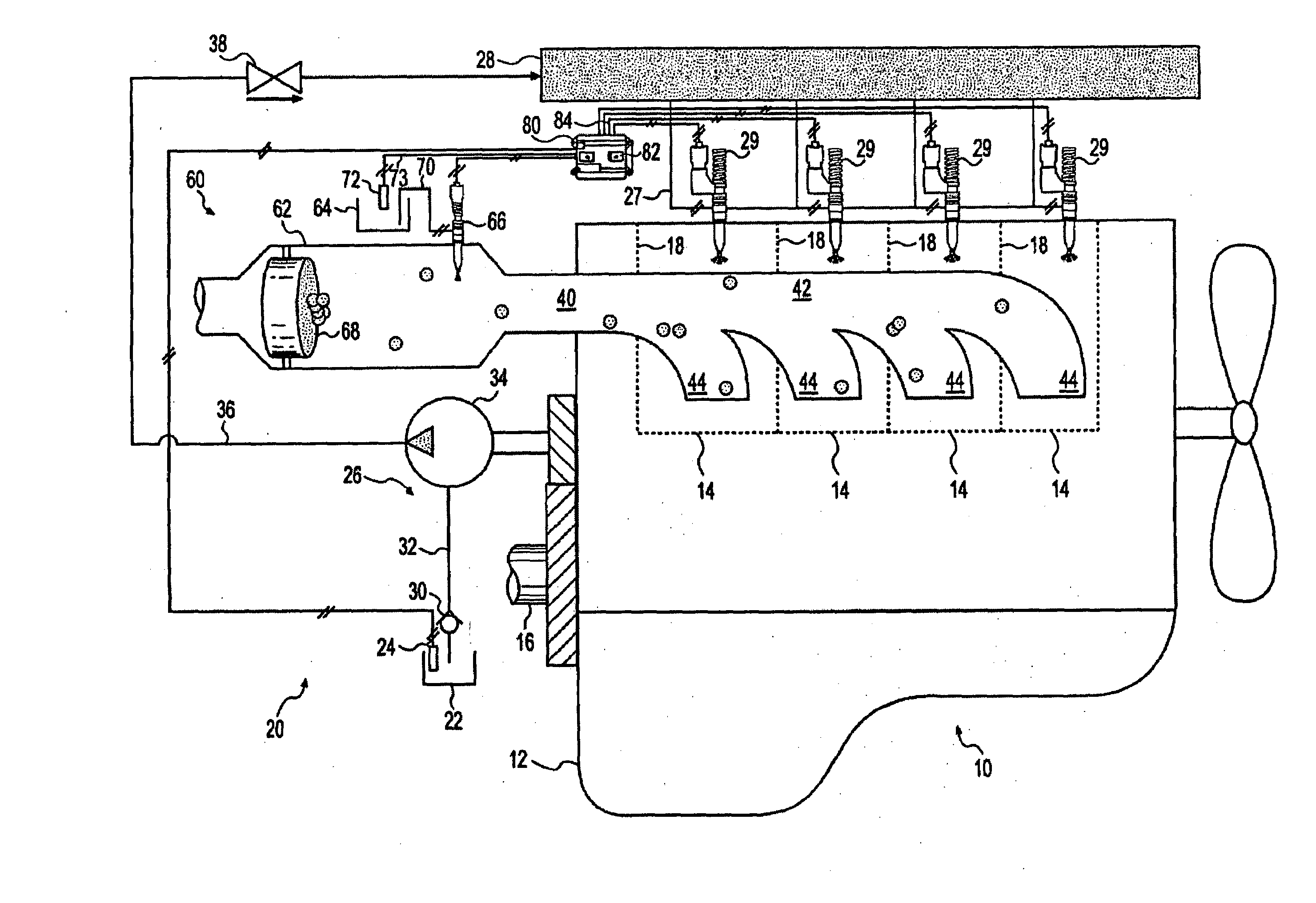
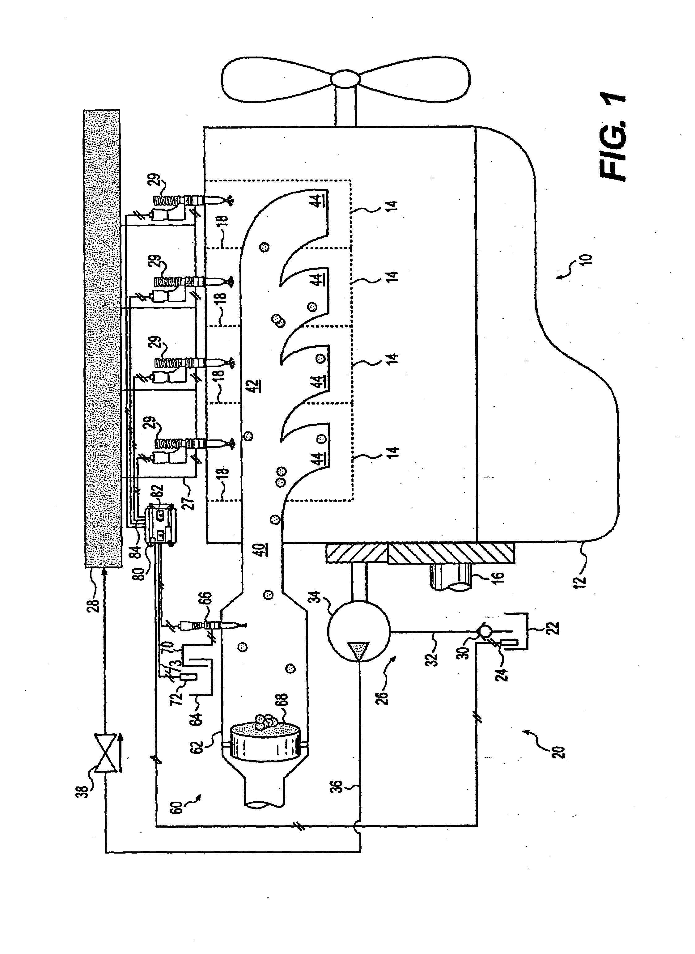
[0014]FIG. 1 illustrates a power unit 10 having a fuel system 20, an exhaust system 40, and an aftertreatment system 60. For the purposes of this disclosure, power unit 10 is depicted and described as a four-stroke diesel engine. One skilled in the art will recognize, however, that power unit 10 may be any other type of internal combustion engine such as, for example, a gasoline engine, a gaseous fuel-powered engine, or a turbine engine. Power unit 10 may include an engine block 12 that at least partially defines a plurality of combustion chambers 14. In the illustrated embodiment, power unit 10 includes four combustion chambers 14. However, it is contemplated that power unit 10 may include a greater or lesser number of combustion chambers 14 and that the combustion chambers 14 may be disposed in an “in-line” configuration, a “V” configuration, or any other suitable configuration.

[0015]As also shown in FIG. 1, power unit 10 may include a crankshaft 16 that is rotatably disposed with...


PUM


Abstract

A control system for a power unit having a supply of fuel and a supply of reductant is disclosed. The control system may have a first sensor associated with the supply of fuel to generate a signal indicative of a quantity of fuel remaining. The control system may also have a second sensor associated with the supply of reductant to generate a signal indicative of a quantity of the reductant remaining. The control system may further have a controller in communication with the first and second sensors. The controller may be configured to affect operation of the power unit such that the remaining fuel is consumed before consumption of the remaining reductant.

Description

TECHNICAL FIELD[0001]The present disclosure is directed to a mode of engine operation and, more particularly, to a system that implements a conservation mode of engine operation in response to low levels of a reductant supply.BACKGROUND[0002]Internal combustion engines, including diesel engines, gasoline engines, gaseous fuel-powered engines, and other engines known in the art exhaust a complex mixture of air pollutants. These air pollutants may be composed of gaseous compounds such as, for example, the oxides of nitrogen (NOx). Due to increased awareness of the environment, exhaust emission standards have become more stringent, and the amount of NOx emitted from an engine may be regulated depending on the type of engine, size of engine, and / or class of engine. In order to ensure compliance with the regulation of these compounds, some engine manufacturers have implemented a strategy called Selective Catalytic Reduction (SCR).[0003]SCR is a process where a gaseous or liquid reductant...

Claims


Application Information

Patent Timeline
IPC IPC(8): F01N3/00
CPCF01N3/2066F01N2610/02F01N2900/08F01N2900/1806F01N2900/1814F02D41/0235Y02T10/24F02D41/401F02D2250/36G01F9/001G01F23/30Y02T10/44F02D41/2422Y02T10/12Y02T10/40
Inventor DONALDSON, GEORGE E.DRISCOLL, JAMES J.
Owner CATERPILLAR INC
Features
  • Generate Ideas
  • Intellectual Property
  • Life Sciences
  • Materials
  • Tech Scout
  • Unparalleled Data Quality
  • Higher Quality Content
  • 60% Fewer Hallucinations
Learn More