Heat pump system and controls

a heat pump and control technology, applied in the field of heat pump systems and controls, can solve the problems of increasing the difficulty of drawing heat from the outdoor environment, reducing the energy cost of consumers, and increasing the difficulty of conventional heat pump systems in colder climates, so as to achieve the effect of increasing the heating capacity and facilitating the discharging

Inactive Publication Date: 2008-05-01
ELECTRO IND
View PDF71 Cites 56 Cited by
  • Summary
  • Abstract
  • Description
  • Claims
  • Application Information

AI Technical Summary

Benefits of technology

[0019]The preferred embodiment of the present invention provides increased heating capacity through the use of a primary compressor, a booster compressor and an economizer. The system effectively utilizes this heating capacity with three heat exchangers that provide 1) indoor air heating or cooling, 2) hydronic floor heating and 3) tap water heating.

Problems solved by technology

Heat pump systems are also highly efficient, resulting in decreased energy costs to the consumer.
The use of conventional heat pump systems in colder climates, however, presents significant challenges.
At very low temperatures, however, it becomes increasingly difficult to draw heat from the outdoor environment.
In addition, at very low temperatures, the outdoor heat exchange coil is very susceptible to frost build up, which limits air flow across the coil.
As a result, the performance and efficiency of heat pump systems decreases drastically at very low ambient temperatures when heating capacity is most needed.
Single compressor systems have been utilized that can provide heating at low to moderate ambient temperatures, but such systems typically demonstrate decreased efficiency and performance at higher

Method used


Image

  • Heat pump system and controls
  • Heat pump system and controls
  • Heat pump system and controls

Examples


Embodiment Construction

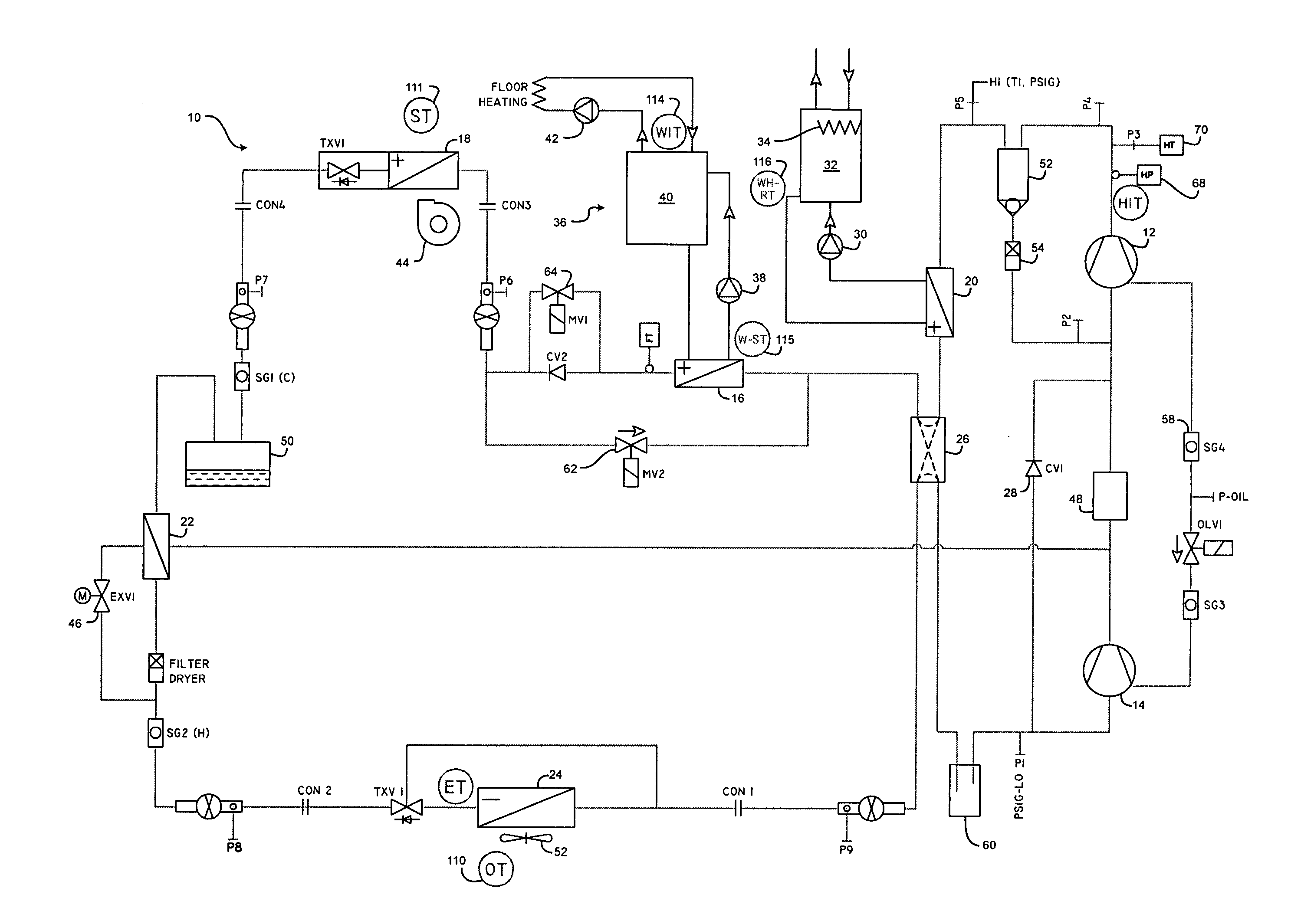
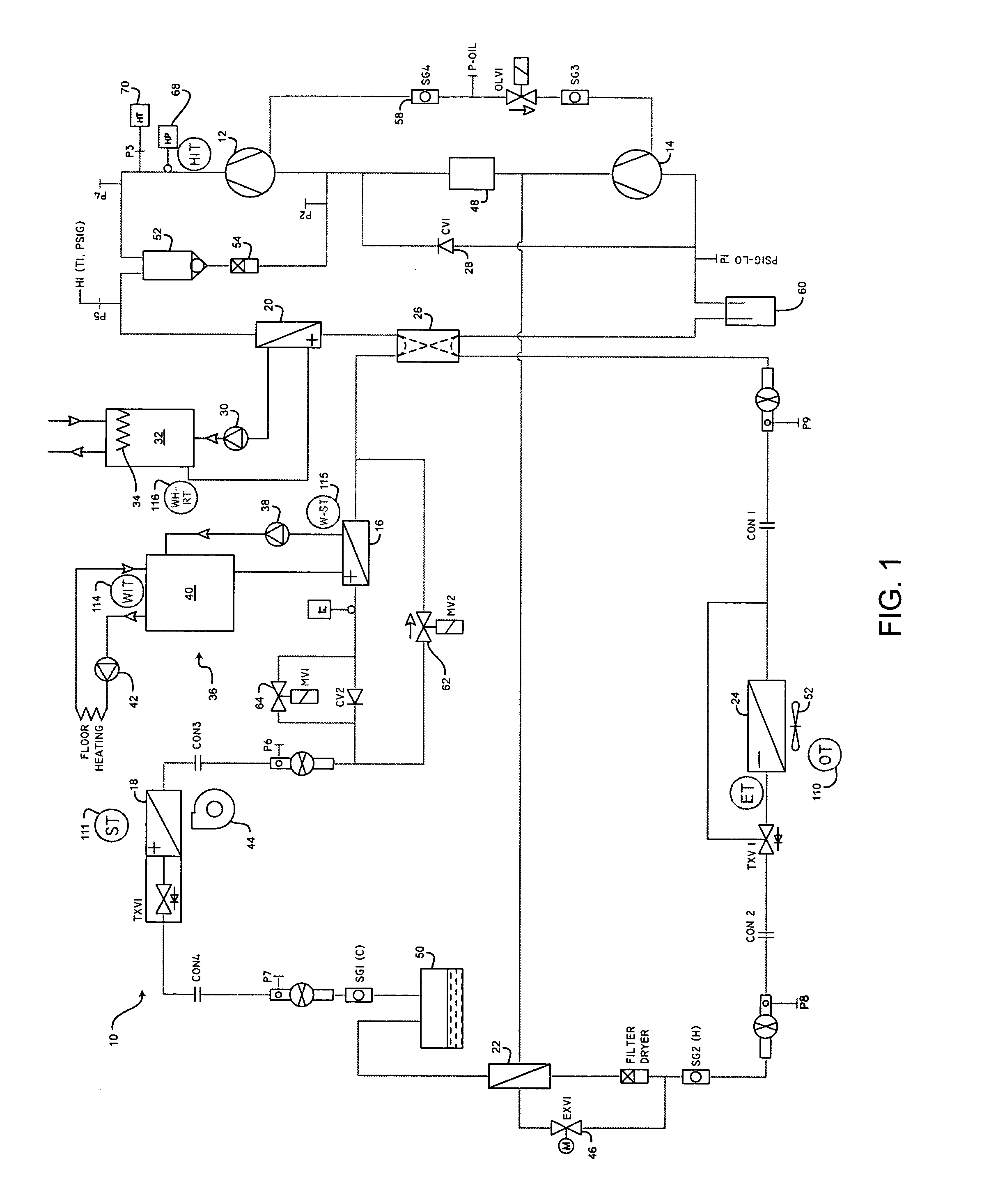
[0028]FIG. 1 is a schematic of one embodiment of the heating and cooling system 10 of the present invention. The primary components of the system include a primary compressor 12, a booster compressor 14, a first condenser 16, a second condenser 18, a third condenser 20, an economizer 22, an evaporator 24 and a 4-way valve 26.

[0029]The primary compressor 12 is preferably a scroll-type two-speed compressor that may be operated at two discrete discharge pressure settings. The booster compressor 14 is preferably a single-speed compressor that may be operated at a single discharge pressure setting. The two compressors may be operated in series or the booster compressor 14 may be bypassed by opening booster compressor bypass valve 28. A temperature sensor (HIT) monitors the temperature and a pressure sensor (HI) monitors the pressure of the refrigerant exiting the primary compressor 12.

[0030]In the preferred embodiment of the present invention, and depending upon the heating and cooling d...


PUM


Abstract

A heat pump system is disclosed that utilizes one or two compressors and multiple heat exchangers to provide forced air heating, radiant heating and/or water heating for an interior space. A controller directs energy to these multiple system outputs to provide maximum comfort, effectively utilize any excess energy, address fluctuations in energy output, prevent unsafe operating conditions and avoid intermittent compressor operation. The system may provide energy for a water heater in both heating and cooling mode, and control operation of the water heater to utilize system energy whenever possible and avoid use of a conventional water heater heating element. Load Management Control is also provided so that the system may be shut down remotely by a utility company.

Description

CROSS-REFERENCE TO RELATED APPLICATION[0001]This application is a Continuation-in-Part of Application Serial No. US 2005 / 0252226 A1, entitled “Heating / Cooling System” and filed May 11, 2005, the contents of which are incorporated herein by reference.FIELD OF THE INVENTION[0002]The present invention relates generally to heating and cooling systems and more specifically to a heating and cooling system with multiple compressors, multiple heat outputs and the control system for managing the system.BACKGROUND OF THE INVENTION[0003]Heat pump systems have found widespread application for heating and cooling homes and businesses. Because heat pump systems utilize the same primary components for both heating and cooling, they eliminate the need for separate heating and cooling systems and are therefore economical to install and use. Heat pump systems are also highly efficient, resulting in decreased energy costs to the consumer. As a result, the demand for heat pump systems in residential an...

Claims


Application Information

Patent Timeline
IPC IPC(8): F25B13/00F25B27/00F25B1/10
CPCF25B1/10F25B2700/21161F25B29/003F25B40/04F25B47/025F25B2313/003F25B2313/008F25B2313/0234F25B2313/02741F25B2339/047F25B2400/0401F25B2400/0403F25B2400/13F25B2600/0252F25B2600/2509F25B2700/1931F25B2700/2104F25B2700/2106F25B2700/21152F25B13/00
Inventor SEEFELDT, WILLIAM J.
Owner ELECTRO IND
Why Eureka
Try Eureka