Spread Spectrum Clock and Reference Signal Generator

a clock signal and frequency reference technology, applied in the direction of generating/distributing signals, instruments, modulation, etc., can solve the problems of inability to manufacture as part of the same integrated circuit, affecting the additional power dissipation, and reducing the efficiency of the signal generation process, etc., to achieve low phase noise and period jitter, low error, and fast rise and fall time

Inactive Publication Date: 2008-05-01
INTEGRATED DEVICE TECH INC
View PDF45 Cites 53 Cited by
  • Summary
  • Abstract
  • Description
  • Claims
  • Application Information

AI Technical Summary

Benefits of technology

[0013] Exemplary embodiments of the invention provide a reference signal generator, system and method which provides a superior reference signal, and which is capable of being fully integrated with other electronics. The exemplary reference signal generator and system provides a very accurate reference and / or clock signal, with very low error, very low phase noise and period jitter, and with extremely fast rise and fall times, rendering the exemplary embodiments suitable for highly exacting applications. The exemplary embodiments also provide for accurate frequency control over variable parameters such as temperature, fabrication process variation, and IC aging. In various exemplary embodiments, the invention provides an apparatus which generates a frequency reference signal, which may be modified directly to generate a spread spectrum reference signal, such as for reducing interference with other signals.

Problems solved by technology

The difficulty with such crystal oscillators is that they cannot be fabricated as part of the same integrated circuit (“IC”) that is to be driven by their clock signal.
For example, because such a processor must be connected through outside circuitry (such as on a printed circuit board (PCB)), power dissipation is comparatively increased.
In applications which rely on a finite power supply, such as battery power in mobile communications, such additional power dissipation is detrimental.
In addition, such non-integrated solutions, by requiring an additional IC, increase space and area requirements, whether on the PCB or within the finished product, which is also detrimental in mobile environments.
Moreover, such additional components increase manufacturing and production costs, as an additional IC must be fabricated and assembled with the primary circuitry (such as a microprocessor).
Other clock generators which have been produced as integrated circuits with other circuits are generally not sufficiently accurate, particularly over fabrication process, voltage, and temperature (“PVT”) variations.
For example, ring, relaxation and phase shift oscillators may provide a clock signal suitable for some low-sensitivity applications, but have been incapable of providing the higher accuracy required in more sophisticated electronics, such as in applications requiring significant processing capability or data communications.
In addition, these clock generators or oscillators often exhibit considerable frequency drift, jitter, have a comparatively low Q-value, and are subject to other distortions from noise and other interference.

Method used


Image

  • Spread Spectrum Clock and Reference Signal Generator
  • Spread Spectrum Clock and Reference Signal Generator
  • Spread Spectrum Clock and Reference Signal Generator

Examples


second embodiment

[0177]FIG. 26 is a circuit and block diagram illustrating an exemplary eighth control voltage generator 700 embodiment in accordance with the teachings of the present invention. In this second embodiment, a temperature sensor 705 is utilized, and the first current source (630 or 631) and the second current source (635 or 632) may be either fixed or variable. In a first method of operating the eighth control voltage generator 700, temperature sensor 705 is utilized to determine the actual operating temperature of the reference signal generator 100, 200, 300, 400, 500, 600. Based on the sensed temperature, a memory 710 (as a look up table) is used to select corresponding control coefficients, which then select the amount of resistance of the variable resistance 655, as discussed above. In various embodiments, the sensed temperature may be used to access the memory 710 directly. In other embodiments, the sensed temperature may be converted from an analog to digital value (analog-to-dig...

first embodiment

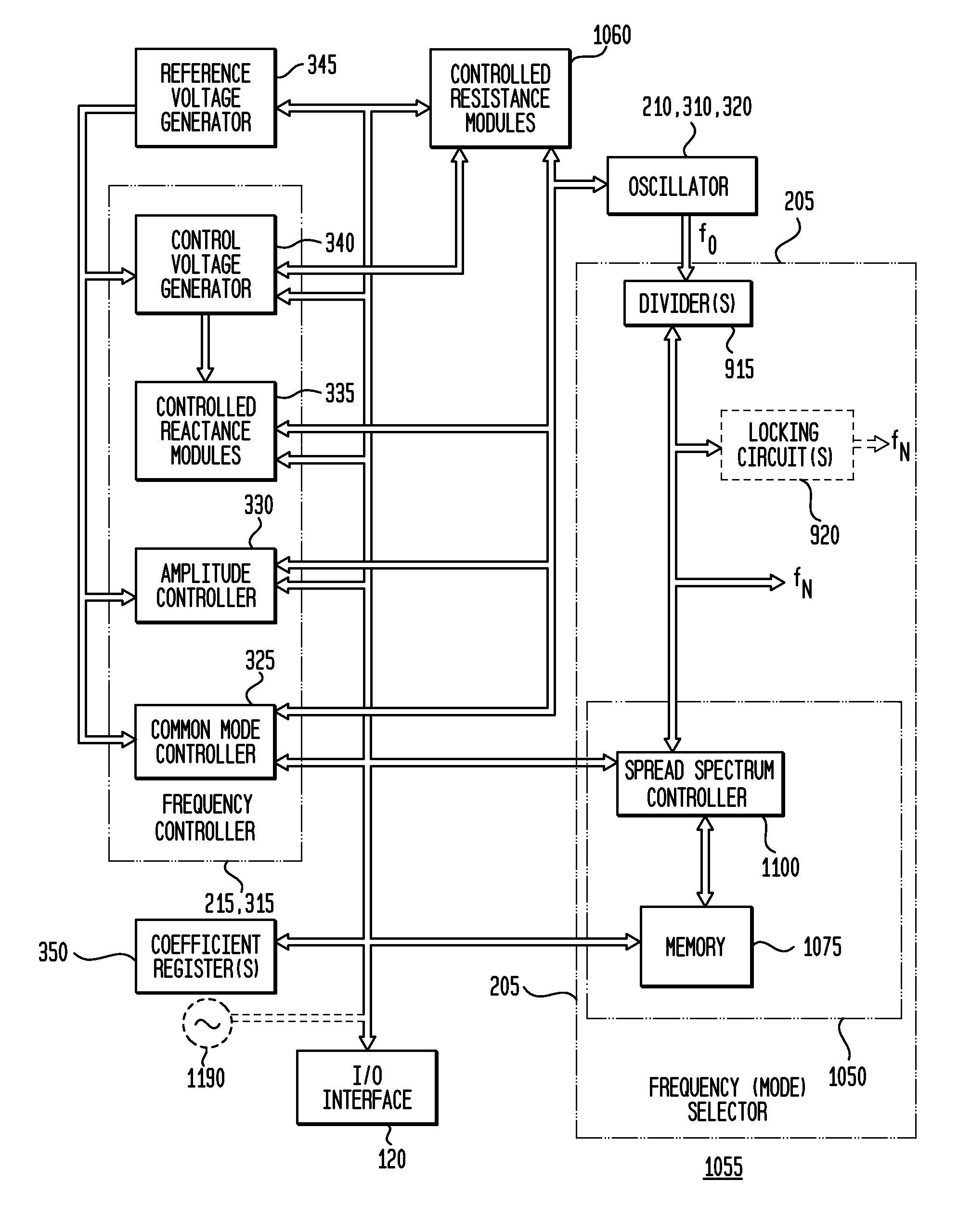
[0218] Referring to these various methods, in a first embodiment, the spread spectrum controller, illustrated as first spread spectrum controller 1100, is adapted to select or modify the control coefficients to provide the spread spectrum functionality of the system 1055. By changing the control coefficients during a spreading (modulation) time period, the spread spectrum controller 1100 modifies the amount of reactance or impedance coupled to the oscillator / resonator (such as by switching a reactance or modifying a control voltage as discussed above) or provides the other variations described above (e.g., changing currents, changing divide ratios), and thereby modifies the reference frequency (or resonant frequency) f0 of the oscillator / resonator, resulting in a range (or plurality) of different reference frequencies occurring or being provided at the spreading modulation rate, such as the range of frequencies about or within fC±x (for center spreading), fC−x (for downspreading), o...


PUM


Abstract

Exemplary embodiments of the invention provide a system, method and apparatus for spread spectrum functionality for a free-running, reference harmonic oscillator. In an exemplary embodiment, an apparatus comprises a reference oscillator adapted to provide a reference signal having a reference frequency; and a spread spectrum controller adapted to control the reference oscillator to generate a spread-spectrum reference signal at a plurality of different reference frequencies during a predetermined or selected time period. An exemplary apparatus may also include a coefficient register adapted to store a plurality of coefficients and a plurality of controlled reactance modules responsive to a corresponding coefficient of the plurality of coefficients to modify an amount of reactance effectively coupled to the reference oscillator. An exemplary spread spectrum controller is further adapted to sequentially modify the plurality of coefficients during the predetermined time period to provide the spread spectrum reference signal.

Description

CROSS-REFERENCE TO RELATED APPLICATIONS [0001] This application is a continuation-in-part of and claims priority to U.S. patent application Ser. No. 11 / 950,707, filed Dec. 5, 2007, inventors Scott Michael Pemia et al., entitled “Clock, Frequency Reference, and Other Reference Signal Generator”, which is commonly assigned herewith, the entire contents of which are incorporated herein by reference with the same full force and effect as if set forth in their entirety herein, and with priority claimed for all commonly disclosed subject matter. [0002] This application is also a continuation-in-part of and claims priority to U.S. patent application Ser. No. 11 / 384,973, filed Mar. 20, 2006, inventors Michael Shannon McCorquodale et al., entitled “Discrete Clock Generator and Timing / Frequency Reference”, which is commonly assigned herewith, the entire contents of which are incorporated herein by reference with the same full force and effect as if set forth in their entirety herein, and with...

Claims


Application Information

Patent Timeline
Patent Type & Authority Applications(United States)
IPC IPC(8): G06F1/08H03B19/05H03B19/03
CPCH03B2200/005H03L5/00H03B5/1228H03B5/1215H03B5/1287H03B5/1265H03B5/1253H03B5/1293H03B5/1243
Inventor PERNIA, SCOTT MICHAELCARICHNER, GORDONMARSMAN, ERICMCCORQUODALE, MICHAEL SHANNON
Owner INTEGRATED DEVICE TECH INC
Why Eureka
Try Eureka