Low Power Direct Conversion Rf Transceiver Architecture and Asic and Systems Including Such

Inactive Publication Date: 2008-05-01
CUSTOM ONE DESIGN
View PDF15 Cites 6 Cited by
  • Summary
  • Abstract
  • Description
  • Claims
  • Application Information

AI Technical Summary

Benefits of technology

[0006]Accordingly, it is a primary object of the present invention to provide a multi-band (mask tunable) RF transceiver design with a significantly enhanced featur

Problems solved by technology

This can present challenges in terms of access.
Circumstances such as bad weather, vegetation, inaccessible landscapes, animals and/or alarms may prevent meter readers from performing their tasks on their first attempt, and may make their jobs more hazardous.
Rescheduling appo

Method used


Image

  • Low Power Direct Conversion Rf Transceiver Architecture and Asic and Systems Including Such
  • Low Power Direct Conversion Rf Transceiver Architecture and Asic and Systems Including Such
  • Low Power Direct Conversion Rf Transceiver Architecture and Asic and Systems Including Such

Examples


Embodiment Construction

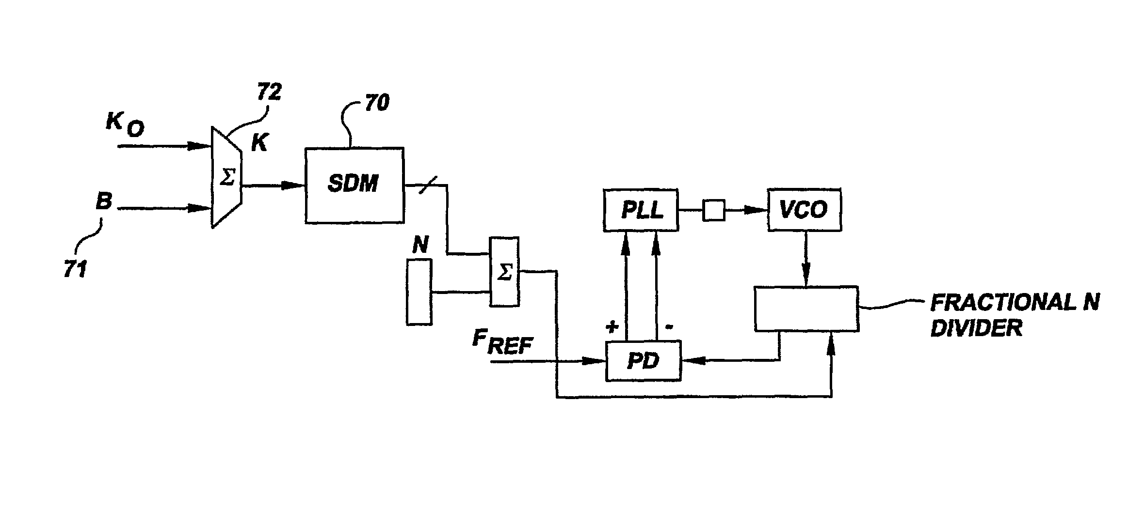
[0022]The RF transceiver architecture described below has been integrated within a single chip for use in telemetering systems and provides multi-band (a single metal mask layer change to tune transceiver to frequencies such as 429 MHz, 952 MHz, 1.2 GHz or 1.43 GHz), battery powered functionality in a small package size (e.g., 9 mm×9 mm or smaller). The ASIC works under microcontroller supervision and provides an on-chip DC-DC converter with novel power boost circuitry to meet increased amperage demands for transmitter power supply during transmission. The DC-DC converter described below significantly prolongs battery life for portable transceivers in which the RF transceiver is utilized, and allows use of low voltage power supplies (e.g., battery voltages to 0.6V.)

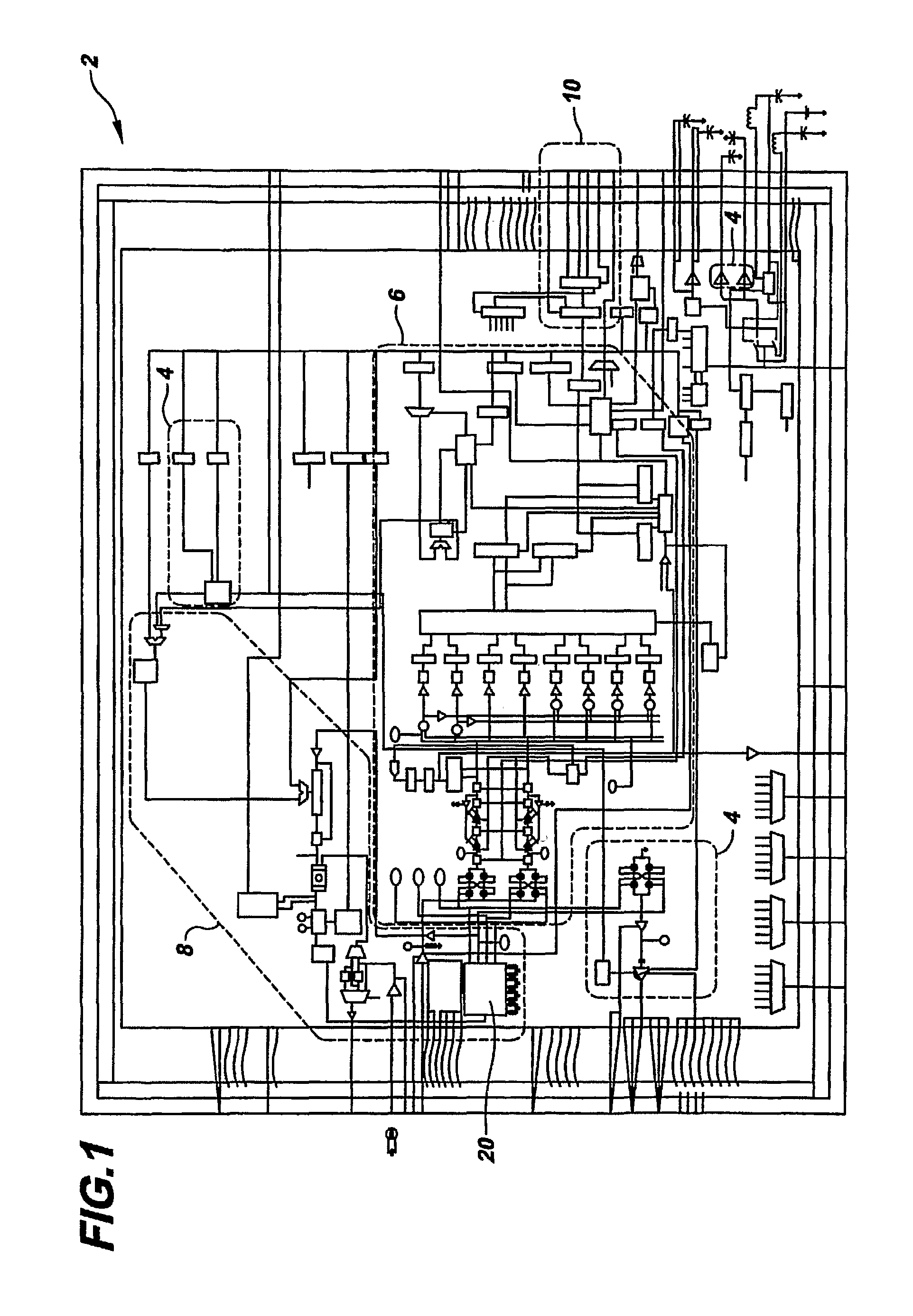
[0023]As shown in the architecture of FIG. 1 the RF transceiver 2 is comprised of the following major circuits: transmitter circuitry (encircled by a dotted line 4); receiver circuitry (encircled by a dotted line 6) inclu...


PUM


Abstract

A direct conversion RF transceiver (2) and ASIC having an on-chip voltage controlled oscillator operating frequency that is half of the transmitter (4) and/or receiver (6) operating frequency, the VCO (20) being comprised of a plurality of synchronized LC oscillators (92A-D) introducing precise phase shifts that eliminate frequency ambiguity. The transceiver incorporates several low power circuits, including on-chip a power converter switchably coupling a capacitor (42) to a power supply (45) and to an electrical load (40), multiple switchable low dropout regulators (60A, B) each coupled to alternate power supplies (62,64) and having electrical components (67A, B) for setting the bandwidth of the respective low dropout regulator. The transceiver also includes a FSK digital modulator utilizing a circuit-implemented polynomial piecewise approximation (71) of a raised cosine signal.

Description

BACKGROUND OF THE INVENTION[0001]The present invention relates generally to low power transmitters, receivers, and transceivers for transmitting and receiving digital information between two or more digital devices, and more particularly to embodiments of multi-band RF transceivers that can be implemented preferably on a single chip and / or for use in applications involving remote reading of metering equipment.[0002]A variety of industries require transmitting and receiving digital circuitry to meet strict power consumption requirements in order to be useful in battery-operated and power-sensitive applications. Examples of such applications include narrow-band & wide-band security systems, voice and data over radiofrequency (RF) links, process and building control, parking & traffic enforcement monitoring, access control, home automation, home appliance interconnections.[0003]In utilities industries, for example, it is often necessary to send employees to customer sites to take physi...

Claims


Application Information

Patent Timeline
IPC IPC(8): H04L27/12G05F1/00H03K3/36H04B1/38H02J1/00H03L3/00H03L7/24H04B1/30H04L7/02
CPCH03L3/00H04L27/12H04B1/30H03L7/24
Inventor NUYTKENS, PETER R.KULINETS, JOSEPH M.
Owner CUSTOM ONE DESIGN
Why Eureka
Try Eureka