Electrical submersible pump

Inactive Publication Date: 2008-05-01
SCHLUMBERGER TECH CORP
View PDF17 Cites 21 Cited by
  • Summary
  • Abstract
  • Description
  • Claims
  • Application Information

AI Technical Summary

Benefits of technology

[0012]In a preferable embodiment, the diffuser spacer made as an element with rigidity in the axial direction but flexible for bending, the impeller spacer has a protrusion, and the ceramic impeller has a mating slot, and besides, has a rounded axis-directed slit that passes the whole inner diameter of the impeller. In the preferable embodiment, the protrusion of the impeller spacer has a flexibility enough to hold a torque. For longer service l

Problems solved by technology

A high rotational speed combined with high solids concentration in the production flow causes accelerated erosion wear of pump stages.
Stage wear also leads to an increase in dynamic loads for journal bearings.
Accelerated wear of radial bearings may be a cause for premature pump failure.
For example, the pump rate growt

Method used


Image

  • Electrical submersible pump
  • Electrical submersible pump
  • Electrical submersible pump

Examples


Embodiment Construction

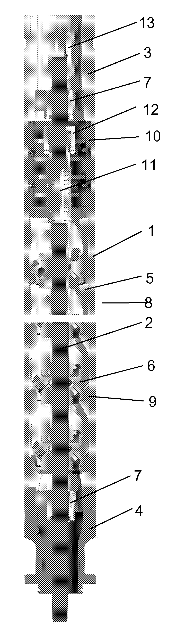
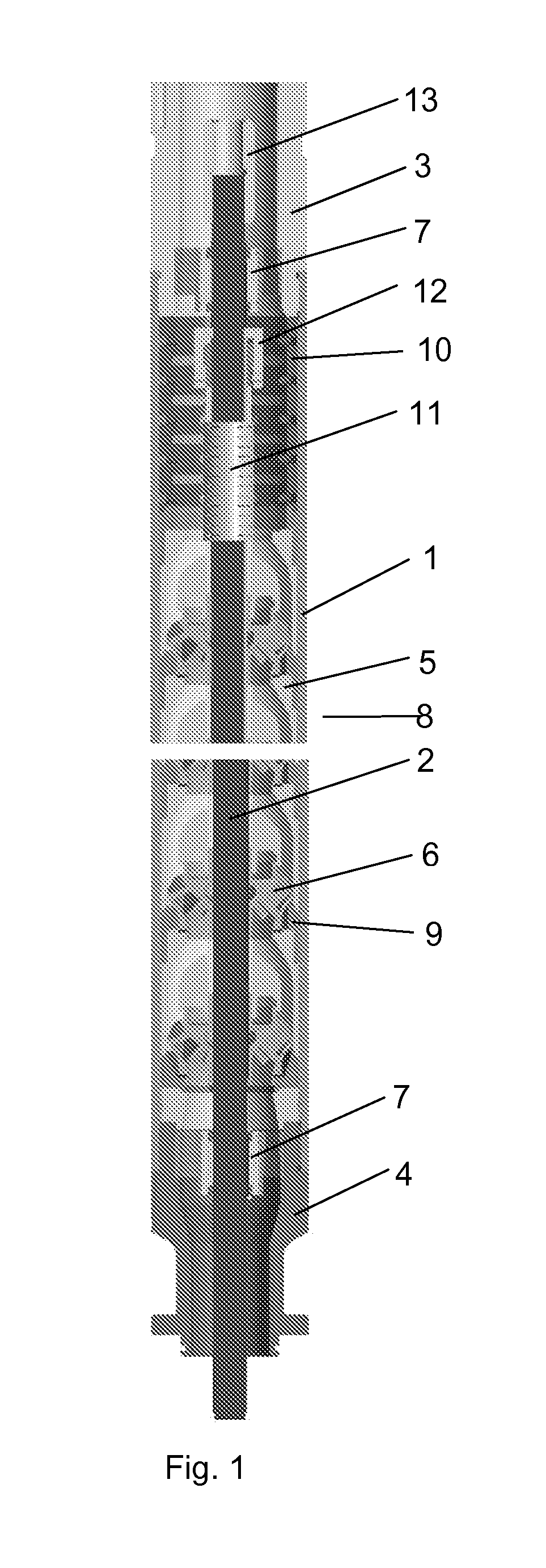
[0020]The erosion-resistant pump section design according to an embodiment of the invention (see FIG. 1) comprises the following components: housing 1, shaft 2, head 3, base 4, diffusers 5, impellers 6, journal bearings 7, impeller spacers 8, diffuser spacers 9, diffuser spring sleeve 10, impeller spring sleeve 11, compression nut 12, and torque spline coupling 13.

[0021]The diffusers stack is compressed inside the housing 1 between the head 3 and the base 4. The compression force magnitude is several tons. The compression force required value is based on the criteria of elimination of gaps between contact surfaces and providing enough friction for preventing diffusers turning inside the housing. The impeller stack is compressed by means of nut 12 on shaft 2. For the impeller stack, the compression force magnitude requirement is much lower—only a few kilograms. A lower compression force in case of impeller stack is explained by the fact that there is a special torque transmission fea...


PUM

PropertyMeasurementUnit
Diameteraaaaaaaaaa
Lengthaaaaaaaaaa
Sizeaaaaaaaaaa

Abstract

The invention relates to high-speed electrical submersible pumps used for hydrocarbons production from oil wells with high concentration of solids. The technical result such as a longer service life is achieved with the technical design, wherein the pump comprises: a housing with a head and a base, a compression nut, a shaft installed on a journal bearing, stages of impellers and spacers installed on the shaft, set of diffusers installed on the housing, wherein the diffusers and impellers are manufactured from a ceramic material. The preferable design has metal spacers between the diffusers, wherein the length of the diffuser spacer between the contact surfaces equals the distance between the impeller spacers.

Description

FIELD OF THE INVENTION[0001]This invention relates to electrical submersible pumps (ESPs) of the type used for production of hydrocarbons from oil wells. In particular, the invention relates to high-speed pumps for use in wells that produce fluids with high concentration of solids.BACKGROUND ART[0002]ESP applications are typically defined as high-speed if the pump shaft is spinning the at a rate over 4500 RPM.[0003]The average formation solids concentration in production flow from Russian wells is about 0.2 g / liter. In case of heavy oil production this parameter can be much higher. The concentration of proppant flowback in production flow can reach concentrations as high as 1 g / liter immediately after fracturing. A high rotational speed combined with high solids concentration in the production flow causes accelerated erosion wear of pump stages. Solids can be trapped inside small gaps between spinning and stationary components of a pump stage to produce abrasion in the stage materia...

Claims


Application Information

Patent Timeline
IPC IPC(8): F04D13/08F04D29/00F04D29/54
CPCF04D7/02F04D13/10F05C2203/08F04D29/2294F04D29/4286F04D29/026F05D2300/20F05D2300/2261F05D2300/2263
Inventor ORBAN, JACQUESGOTLIB, MIKHAIL
Owner SCHLUMBERGER TECH CORP
Why Eureka
Try Eureka