Reforming apparatus for fuel cells

a fuel cell and apparatus technology, applied in the direction of liquid-gas reaction of thin-film type, gas-gas reaction process, separation process, etc., can solve the problems of difficult to absorb carbon dioxide gas at a high temperature, degrade battery function, and electrode poisoning, so as to improve the hydrogen conversion rate , the effect of saving equipment cost and spa

Inactive Publication Date: 2008-05-01
MURATA MFG CO LTD
View PDF3 Cites 7 Cited by
  • Summary
  • Abstract
  • Description
  • Claims
  • Application Information

AI Technical Summary

Benefits of technology

[0045] The reforming apparatus for fuel cells may further include an additional reformer for steam-reforming again the reformed gas from which carbon dioxide has been removed by the carbon dioxide removing apparatus. In this case, steam reforming is carried out again after carbon dioxide gas has been removed, and the reactions of the formulae (1) and (2) can be allowed to further proceed in the reformer, thereby further improving the hydrogen conversion rate.
[0046] Further, in another reforming apparatus for fuel cells which produces hydrogen using a steam reforming method, a reformer for steam reforming is filled with a carbon dioxide absorbent containing Ba2TiO4 as a main component so that the carbon dioxide produced by steam reforming is removed by absorption by the carbon dioxide absorbent filling the reformer. Therefore, the carbon dioxide which inhibits the formation of hydrogen by steam reforming can be rapidly removed in the reformer, and the reactions of the above formulae (1) and (2) can be allowed to proceed in the reformer, thereby further improving the hydrogen conversion rate.
[0047] An advantage is that carbon dioxide removing equipment need not be separately provided, and thus the equipment cost and space can be saved.

Problems solved by technology

Among these gases, CO poisons electrodes and degrades the battery function when the reformed gas is used for a fuel cell.
However, in this method, even when the absorbent is used, under actual conditions, it is difficult to absorb carbon dioxide gas at a high temperature (e.g., over 700° C.) at which the steam reforming reaction is actually performed.
However, it is difficult to decrease the CO concentration to 1% or less in the gas after absorption of carbon dioxide, and use of the proton-exchange membrane fuel cell (PEFC) requires a CO converter provided in front of the selective oxidation reactor.
However, in order to absorb carbon dioxide gas at 800° C. using CaO, a necessary carbon dioxide concentration is about 40%, and it is difficult to decrease the carbon dioxide concentration to 10% or less even by absorbing carbon dioxide gas at 750° C. Further, in view of the fact that the carbon dioxide gas concentration after steam reforming is generally about 10%, it is thought to be actually difficult to absorb carbon dioxide gas with CaO under the steam reforming conditions.
In addition, as in the above-mentioned method using Li2ZrO3 or Li4ZrO4, it is difficult to decrease the CO concentration to 10% or less in the gas after absorption of carbon dioxide even in the temperature region of 700° C. or less in which carbon dioxide can be absorbed, and the use of the proton-exchange membrane fuel cell (PEFC) requires a CO converter provided in front of the selective oxidation reactor.
When CaO or Li containing oxide such as Li2ZrO3 or Li4ZrO4 is used as the carbon dioxide absorbent as before, it is difficult to efficiently absorb carbon dioxide.

Method used


Image

  • Reforming apparatus for fuel cells
  • Reforming apparatus for fuel cells
  • Reforming apparatus for fuel cells

Examples


example 1

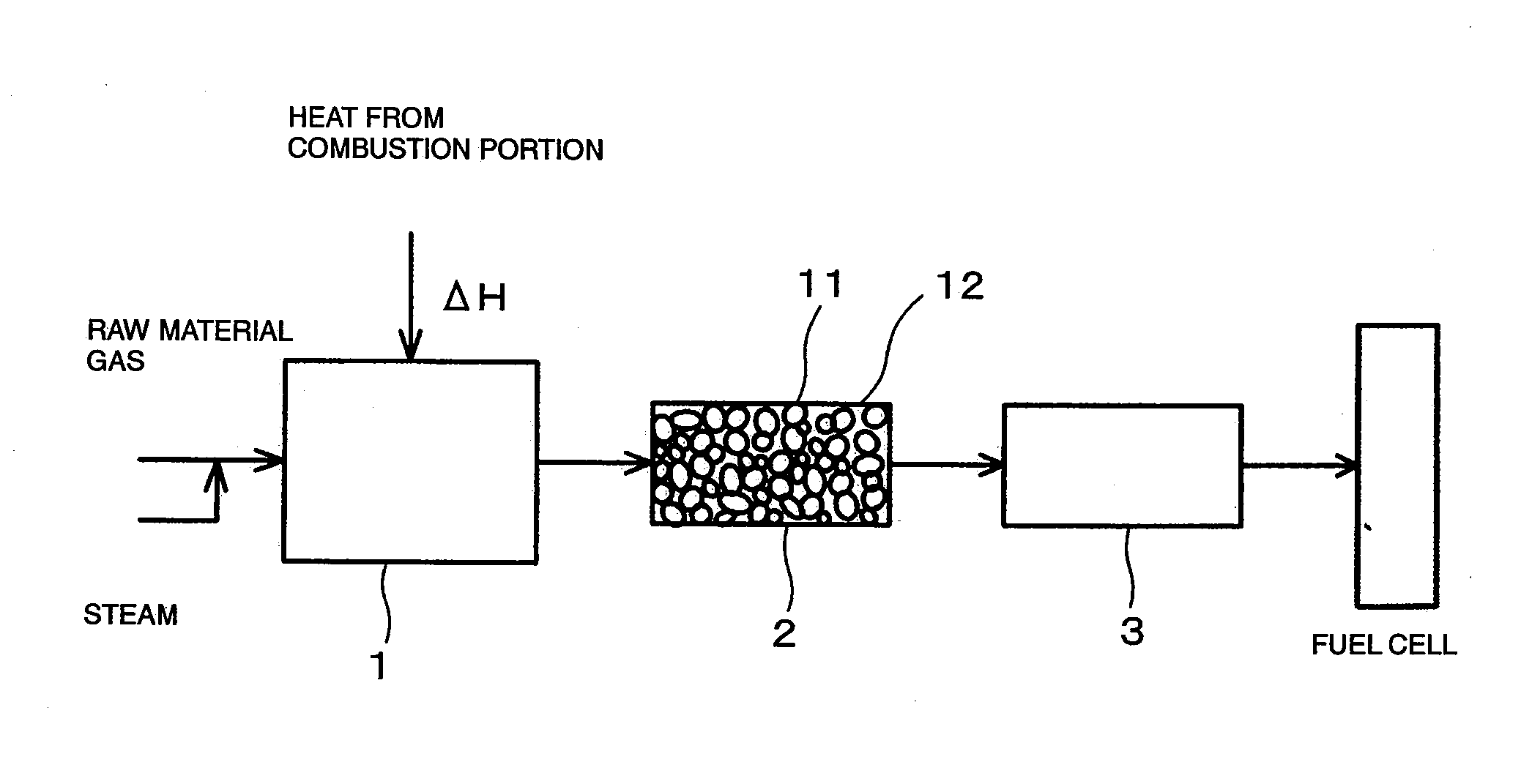
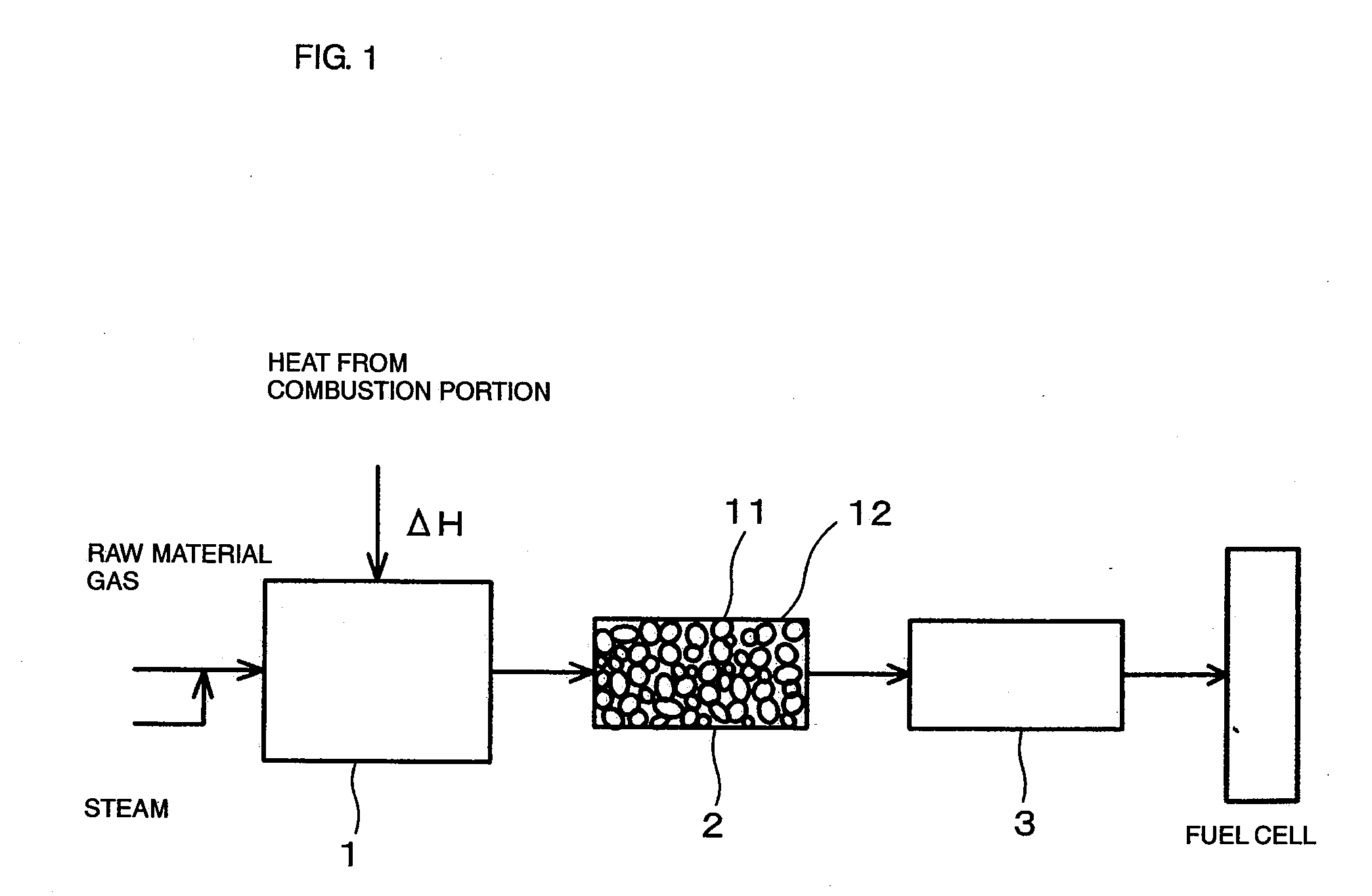
[0070]FIG. 1 is a drawing showing the constitution of a hydrogen producing apparatus for fuel cells (reforming apparatus for fuel cells) according to an embodiment of the present invention.

[0071] As shown in FIG. 1, the reforming apparatus for fuel cells includes a reformer 1 for steam-reforming a raw material gas (in this example, CH4) to produce hydrogen, a carbon dioxide removing apparatus 2 for absorbing and removing carbon dioxide gas generated from the reformed gas at a high temperature, which is produced by reforming in the reformer 1, and a CO converter 3 for removing carbon monoxide (CO) in the reformed gas after removal of the carbon dioxide.

[0072] The reformer 1 uses a Ni-based catalyst as a reforming catalyst and is adapted for steam reforming using heat generated by burning a combustion gas in a combustion portion. Since a sulfur compound is harmful to the reforming catalyst, a raw material gas is introduced into the reformer 1 after being passed through a desulfurize...

example 2

[0089] The same raw material gas (hydrocarbon (CH4)) as in Example 1 was steam-reformed under the same conditions as in Example 1 except that the internal temperature of the reformer 1 was set to 720° C., and then the reformed gas discharged from the reformer 1 was supplied to the carbon dioxide removing apparatus 2 for removing carbon dioxide by absorption. The temperature of the reformed gas at the inlet of the carbon dioxide removing means (carbon dioxide absorber) 2 was 700° C.

[0090] Also, the composition (concentrations of H2, CO, CO2, and hydrocarbon (CH4)) of the reformed gas was measured after passing through the carbon dioxide removing apparatus (carbon dioxide absorber) 2.

[0091] The results were as following.

[0092] (1) Composition of the reformed gas after passing through the carbon dioxide removing apparatus [0093] H2: about 93 vol % [0094] CO: 0.4 vol % [0095] CO2: 0.2 vol % [0096] Hydrocarbon (CH4): 6 vol %

example 3

[0097] The same raw material gas (hydrocarbon (CH4)) as in Example 1 was steam-reformed under the same conditions as in Example 1 except that the internal temperature of the reformer 1 was set to 700° C., and then the reformed gas discharged from the reformer 1 was supplied to the carbon dioxide removing apparatus 2 for removing carbon dioxide by absorption. The temperature of the reformed gas at the inlet of the carbon dioxide removing apparatus (carbon dioxide absorber) 2 was 661° C.

[0098] Also, the composition (concentrations of H2, CO, CO2, and hydrocarbon (CH4)) of the reformed gas was measured after passing through the carbon dioxide removing apparatus (carbon dioxide absorber) 2.

[0099] The results were as following.

[0100] (1) Composition of the reformed gas before passing through the carbon dioxide removing apparatus [0101] H2: about 67 vol % [0102] CO: 13 vol % [0103] CO2: 11 vol % [0104] Hydrocarbon (CH4): 9 vol %

[0105] (2) Composition of the reformed gas after passing ...


PUM

PropertyMeasurementUnit
temperatureaaaaaaaaaa

Abstract

A reforming apparatus for fuel cells capable of effectively removing carbon dioxide at a high temperature from a reformed gas which is produced by a steam reforming method, and of producing high-purity hydrogen gas with a high hydrogen conversion rate. A reforming apparatus for fuel cells includes a reformer for steam-reforming a raw material to produce hydrogen, and carbon dioxide removing apparatus for removing carbon dioxide gas by absorbing carbon dioxide from a reformed gas, which is produced by steam reforming in the reformer, using a material containing Ba2TiO4 as a main component as a carbon dioxide absorbent. The reforming apparatus for fuel cells may further include a second reformer for steam-reforming again the reformed gas from which carbon dioxide gas has been removed by the carbon dioxide gas removing means. Alternatively, the reformer for steam reforming may enclose the carbon dioxide removing apparatus which uses the carbon dioxide absorbent containing Ba2TiO4 as a main component so that carbon dioxide produced by steam reforming is removed by absorption within the reformer.

Description

CROSS-REFERENCE TO RELATED APPLICATIONS [0001] This is a continuation under 35 U.S.C. §111(a) of PCT / JP2006 / 308230 filed Apr. 19, 2006, and claims priority of JP2005-185569 filed Jun. 24, 2005, and JP2005-269058 filed Sep. 15, 2005, incorporated by reference.BACKGROUND [0002] 1. Technical Field [0003] The present disclosure relates to a reforming apparatus for fuel cells for producing hydrogen using a steam reforming method, and more particularly relates to a reforming apparatus for fuel cells including a carbon dioxide removing apparatus for removing carbon dioxide from a reformed gas at a high temperature. [0004] 2. Background Art [0005] For producing hydrogen used for fuel cells, a known method is the steam reforming method in which, for example, as shown in FIG. 5, steam reforming is performed at a high temperature to produce hydrogen from a raw material gas and steam which are supplied to a reforming portion (reformer) 52 adapted for steam reforming using heat energy which is g...

Claims


Application Information

Patent Timeline
Patent Type & Authority Applications(United States)
IPC IPC(8): C01B3/02B01J19/00
CPCH01M8/0618C01B2203/146H01M8/0668Y02C10/04Y02C10/08Y02E60/50B01D53/02B01D53/62B01D2253/112B01D2256/16B01D2257/504B01D2258/0208C01B3/382C01B3/384C01B3/56C01B2203/0233C01B2203/042C01B2203/047C01B2203/0475C01B2203/066C01B2203/0811C01B2203/1058C01B2203/1064C01B2203/1241C01B2203/1258C01B2203/142H01M8/0631Y02P20/151Y02C20/40
Inventor SAITO, YOSHINORISAKABE, YUKIO
Owner MURATA MFG CO LTD
Why Eureka
Try Eureka