Power plants that utilize gas turbines for power generation and processes for lowering co2 emissions

a gas turbine and power generation technology, applied in the direction of machines/engines, separation processes, mechanical equipment, etc., can solve the problems of large, expensive and energy-intensive co2 removal units, large and expensive cosub>2 /sub>removal devices, etc., and achieve the effect of lowering co2 emission and co2 emissions

Active Publication Date: 2008-05-08
GENERAL ELECTRIC CO +1
View PDF15 Cites 147 Cited by
  • Summary
  • Abstract
  • Description
  • Claims
  • Application Information

AI Technical Summary

Benefits of technology

[0007]Disclosed herein are power plants that employ gas turbines and methods for lowering CO2 emission in the power plant that utilize fossil fuels for power generation. The method of generating energy in a power plant including a gas turbine comprises generating a flue gas from a gas turbine, wherein the gas turbine comprises a compression section having at least two stages comprising a low-pressure compressor and a high-pressure compressor, a combustion section fluidly coupled to the compression section, and an expander fluidly coupled to the combustion section; recirculating the flue gas to the low-pressure compressor; diverting a portion of the recirculated flue gas to a carbon dioxide (CO2) separator and a remaining portion to the high-pressure compressor; separating CO2 from the diverted portion in a CO2 separator to generate a CO2 lean gas; and feeding the remaining portion of the recirculated flue gas to the high-pressure compressor.
[0008]A power plant configured for lowering CO2 emissions comprises a gas turbine comprising a compression section having at least two stages, the at least two compression stages comprising a low-pressure compressor fluidly coupled to a high-pressure compressor; a combustor having a first inlet adapted for receiving compressed gas, a second inlet adapted for receiving fuel and an outlet adapted for discharging hot flue gas; and a main expander section having an inlet adapted for receiving the hot flue gas and an outlet, the outlet of the main expander fluidly coupled to the low-pressure compressor; and a CO2 separator fluidly coupled to the low-pressure compressor for receiving a portion of the flue gas from the low-pressure compressor and provide a CO2 lean gas that is then fed to an additional expander, wherein a remaining portion of the flue gas is provided directly to the high-pressure compressor via the low-pressure compressor being fluidly coupled to the high-pressure compressor.
[0009]In another embodiment, the power plant configured for lowering CO2 emissions comprises a gas turbine comprising a compression section having at least two stages, the

Problems solved by technology

Today's CO2 removal technologies concentrate on CO2 clean up of the atmospheric flue gas stream of a power plant, which results in very large, costly and energy intensive CO2 removal units.
The main disadvantage of the post-combustion CO2 capture processes is that the CO2 partial pressure is very low on account of the low CO2 concentration in the flue gas (typically 3-4% by volume for

Method used


Image

  • Power plants that utilize gas turbines for power generation and processes for lowering co2 emissions
  • Power plants that utilize gas turbines for power generation and processes for lowering co2 emissions
  • Power plants that utilize gas turbines for power generation and processes for lowering co2 emissions

Examples


Embodiment Construction

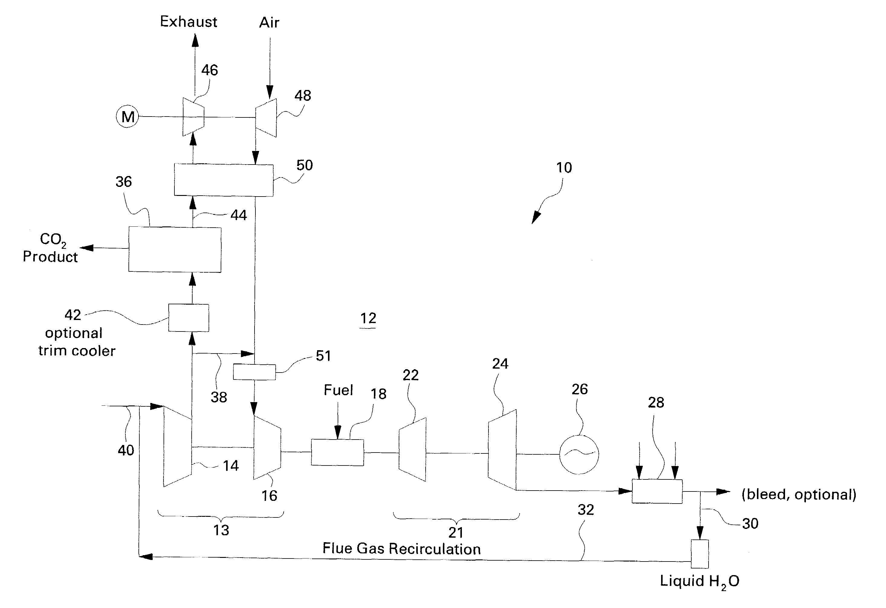
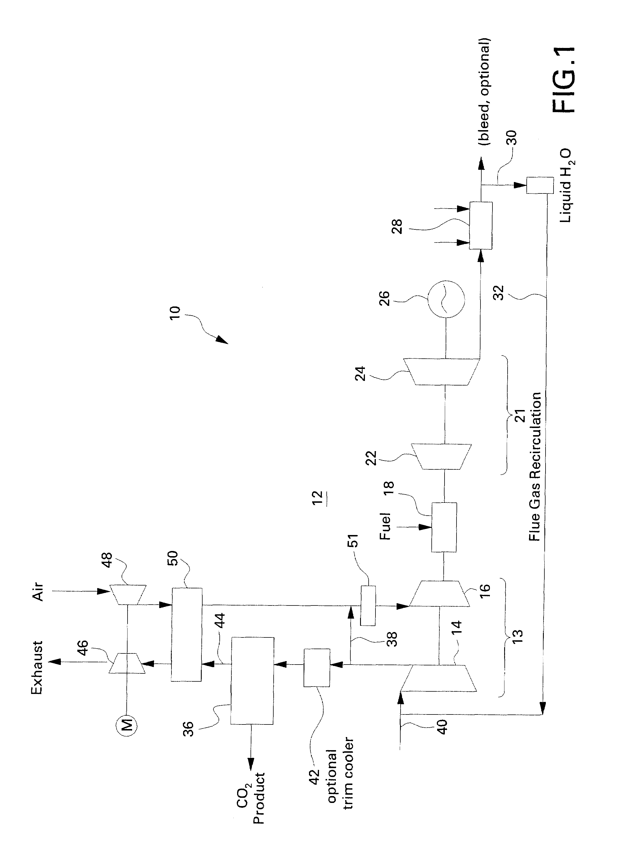
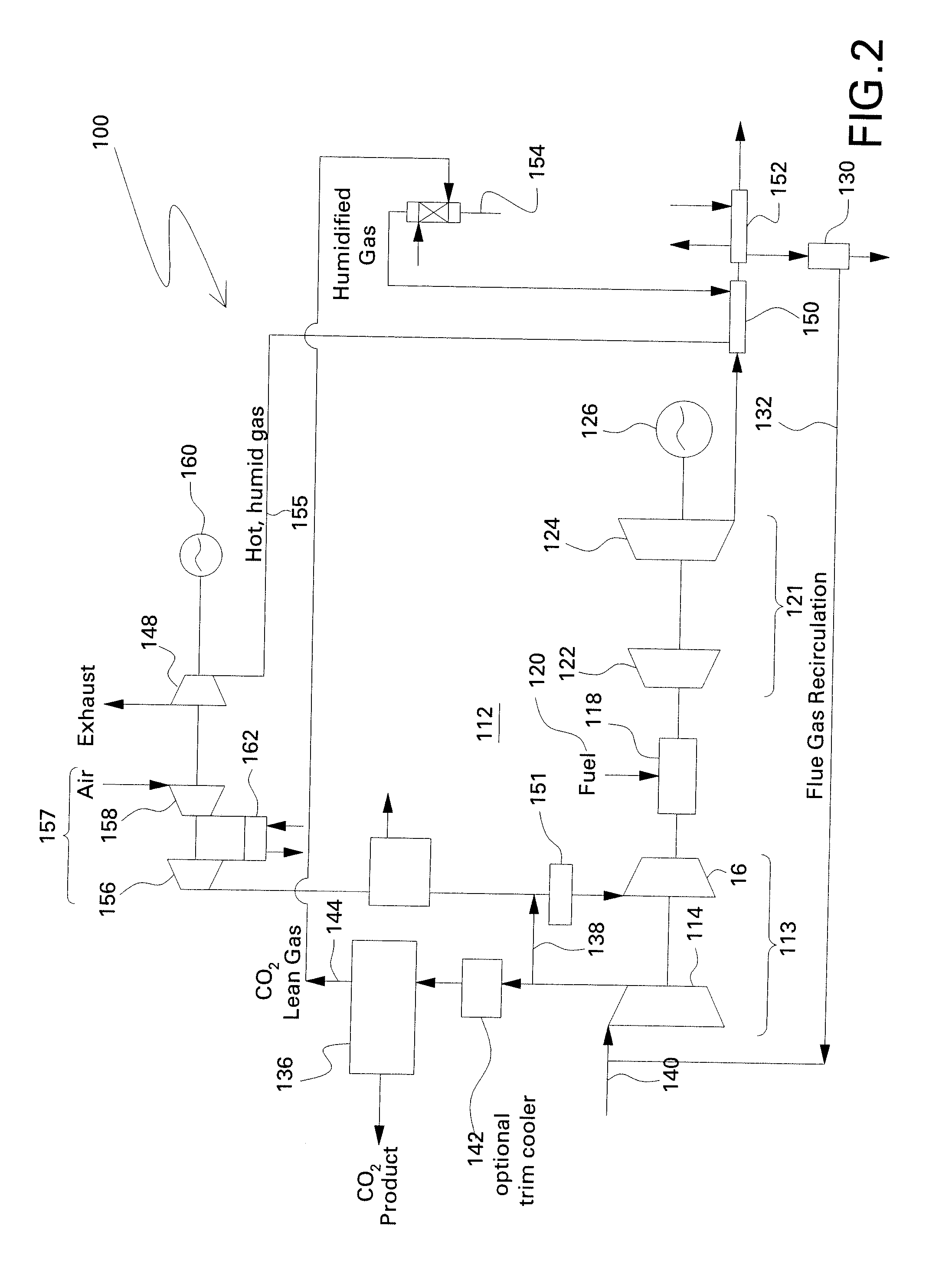
[0016]The present disclosure provides a process for lowering CO2 emissions by separation of CO2 at high-pressures and concentrations in a power plant that utilizes gas turbines for power generation. As will be discussed in greater detail below, high gas pressures are achieved by extracting recirculated CO2-rich flue gas mid-way through the compression pathway of a gas turbine. As a result, flue gas recirculation increases the CO2 concentration within the working fluid, leading to an additional increase in CO2 partial pressure. As the concentration and partial pressure of CO2 is increased, a lower energy penalty is observed to remove the CO2. In addition, due to the CO2 separation at pressure, the volume flows to be treated are significantly reduced compared to atmospheric processes. Consequently, the size of the separation equipment can be reduced as well as the energy required for the separation. In addition, the significant increase in CO2 partial pressure also allows for the sele...


PUM


Abstract

Power plants and process for lowering CO2 emissions generally includes extracting a portion of the recirculated CO2-rich flue gas mid-way through the compression pathway of a gas turbine and removing the CO2 in a separation unit. The remaining portion of the CO2 rich flue gas (i.e., the portion of the recirculated flue gas that was not fed to the separation unit) is mixed with fresh air coming from an additional compressor-expander and then fed back to the compression pathway. As a result, flue gas recirculation increases the CO2 concentration within the working fluid, leading to an additional increase in CO2 partial pressure. As the concentration and partial pressure of CO2 is increased, a lower energy penalty is observed to remove the CO2. Moreover, a reduced volume is fed to the CO2 separation unit during operation. Consequently, the size of the separation equipment can be reduced as well as the energy required for the separation process.

Description

BACKGROUND[0001]The present disclosure generally relates to a process for lowering CO2 emissions in a power plant utilizing fossil fuels for power generation.[0002]Carbon dioxide (CO2) emissions from power plants utilizing fossil fuels are increasingly penalized by national and international regulations, such as the Kyoto protocol, and the EU Emission Trading Scheme. With increasing cost of emitting CO2, CO2 emission reduction is important for economical power generation. Today's CO2 removal technologies concentrate on CO2 clean up of the atmospheric flue gas stream of a power plant, which results in very large, costly and energy intensive CO2 removal units.[0003]Gas turbine plants operate on the Brayton cycle, which generally uses a compressor to compress the inlet air upstream of a combustion chamber. Then the fuel is introduced and ignited to produce a high temperature, high-pressure gas that enters and expands through the turbine section. The turbine section powers both the gene...

Claims


Application Information

Patent Timeline
IPC IPC(8): F02B33/44
CPCB01D53/00B01D2257/504B01D2258/01F02C1/08Y02T10/16F02C3/30F02C3/34Y02C10/04Y02C10/06F02C3/02Y02T10/12Y02C20/40F02C7/08F02G3/00
Inventor FINKENRATH, MATTHIASBARTLETT, MICHAELLYNGHJEM, ARNEJAKOBSEN, JON
Owner GENERAL ELECTRIC CO
Why Eureka
Try Eureka