Manufacture or membrane electrode assembly with edge protection for PEM fuel cells

a technology of pem fuel cells and membrane electrodes, which is applied in the field of fuel cells, can solve the problems of insufficiently satisfying conventional methods of attaching the subgasket to the ionomer membrane, precious metal particles, and high cost of catalysts

Inactive Publication Date: 2008-05-08
GM GLOBAL TECH OPERATIONS LLC
View PDF7 Cites 32 Cited by
  • Summary
  • Abstract
  • Description
  • Claims
  • Application Information

AI Technical Summary

Problems solved by technology

The catalytic particles are typically costly precious metal particles.
These membrane electrode assemblies are relatively expensive to manufacture and require certain conditions, including proper water management and humidification, and control of catalyst fouling constituents such as carbon monoxide (CO), for effective operation.
However, conventional methods of attaching the subgasket to the ionomer membrane have not been completely satisfactory.
In addition to the heat and pressure required in the technique, an additional disadvantage is that the catalyst layers are added after the subgasket.
The subgasket can be attached under the catalyst in this method, but this will often lead to catalyst cracking and delaminating at the subgasket edge.
This cracking results in a fuzzy catalyst edge at the subgasket edge.
Additionally, this method could leave gaps of exposed ionomer membrane between the catalyst and subgasket edges.
First, the heat and pressure required to get the bond can cause the ionomer membrane to flow, which can lead to thinning under the subgaskets.
Second, the heat / cool cycles can induce thermal stresses in the part.
Failures can then occur at the subgasket edge.
Third, because the entire MEA, including the gas diffusion medium (GDM), is assembled in one hot press step, it is very difficult to then inspect the catalyst edge positions.

Method used


Image

  • Manufacture or membrane electrode assembly with edge protection for PEM fuel cells
  • Manufacture or membrane electrode assembly with edge protection for PEM fuel cells
  • Manufacture or membrane electrode assembly with edge protection for PEM fuel cells

Examples


Embodiment Construction

[0019]The following description of the preferred embodiment(s) is merely exemplary in nature and is in no way intended to limit the invention, its application, or uses.

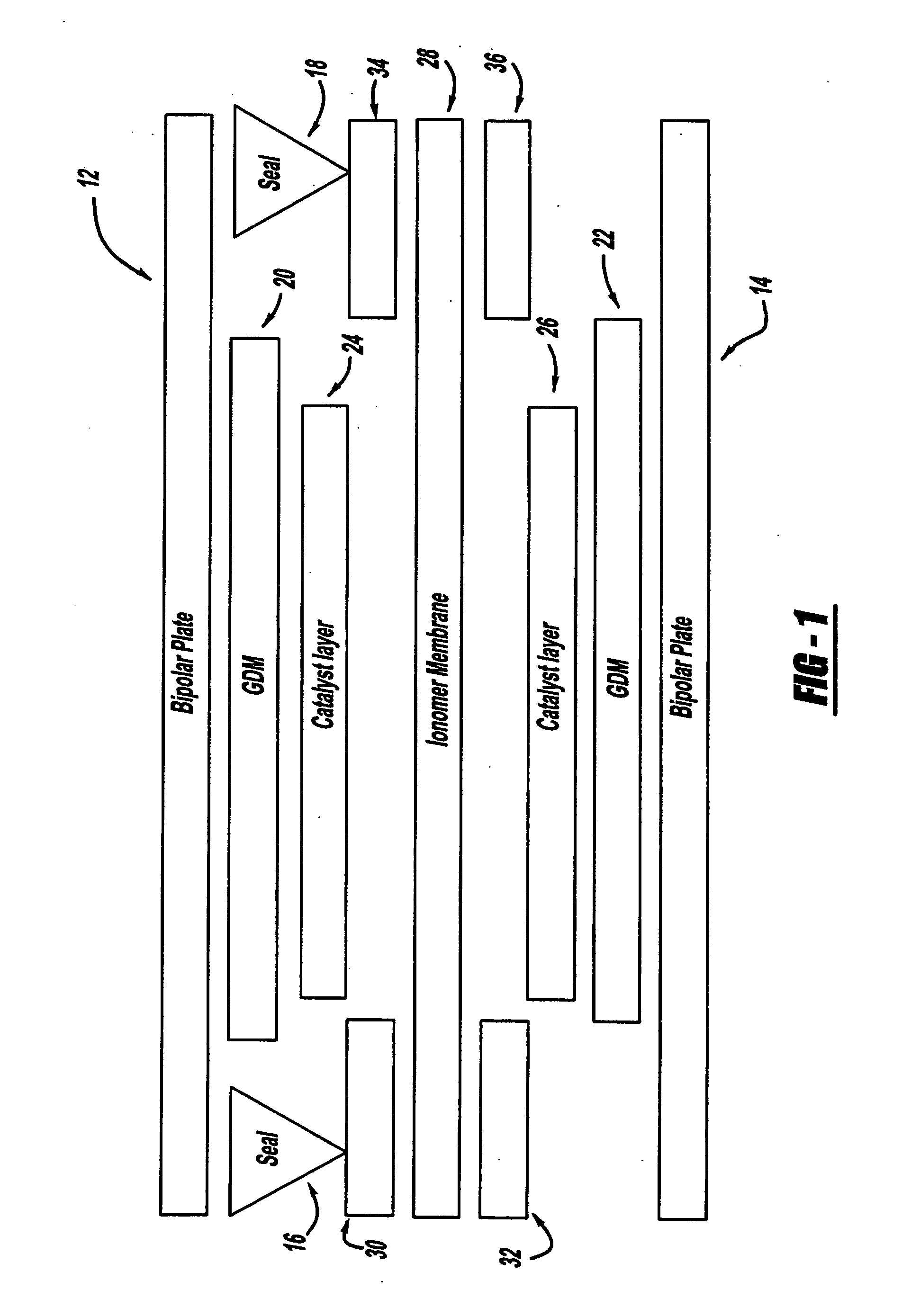
[0020]A typical PEM fuel cell 10, e.g., as shown in FIG. 1, is composed of a pair of spaced and opposed bipolar plates, 12, 14, respectively, a pair of spaced and opposed seals, 16, 18, respectively, two spaced and opposed gas diffusion medium layers 20, 22, respectively, two spaced and opposed catalyst layers, 24, 26, respectively, an ionomer membrane 28, and optionally, some type of subgasket material 30, 32, 34, 36, respectively. As noted, the subgasket is optional and can appear on one or both sides of the ionomer membrane 28. The location of the subgasket relative to the ionomer membrane 28 edges and the catalyst layers 24, 26, respectively, edges is also variable depending on the function of the subgaskets.

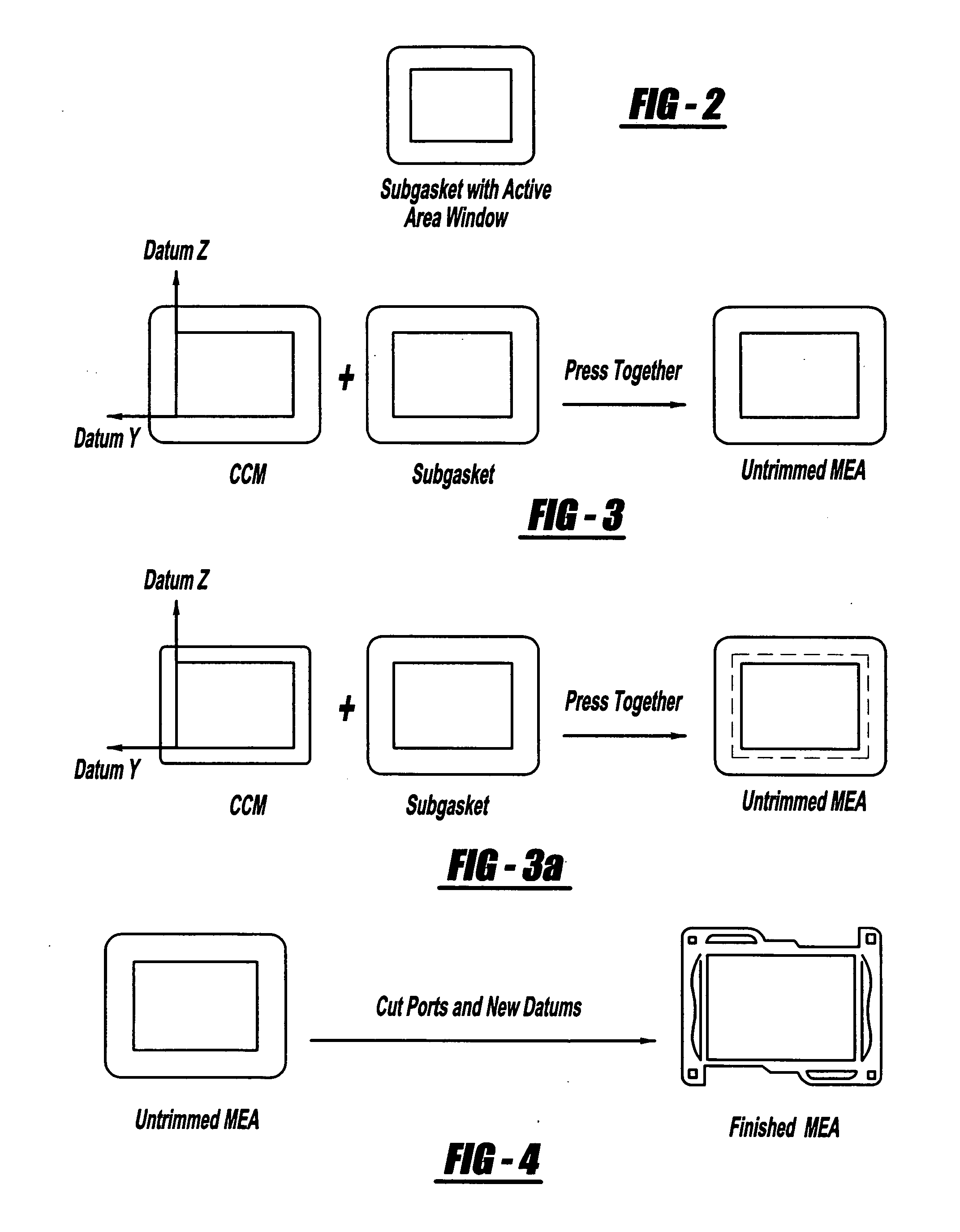
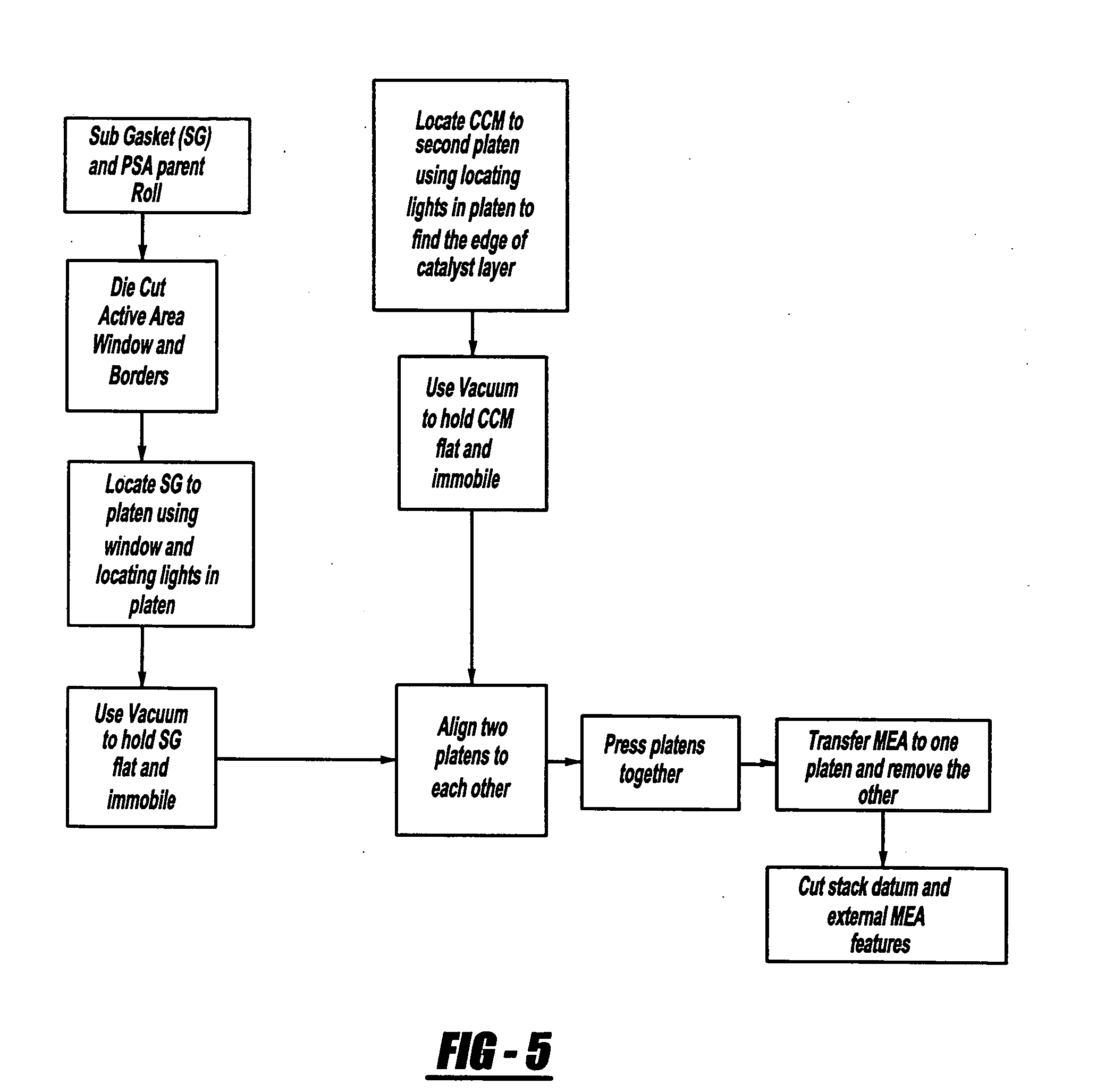
[0021]The present invention primarily relates to methods for attaching a subgasket to an ionomer membrane. ...


PUM

PropertyMeasurementUnit
areaaaaaaaaaaa
pressure sensitiveaaaaaaaaaa
vacuum forceaaaaaaaaaa

Abstract

Methods for attaching a subgasket to an ionomer membrane, wherein the methods provide for the precise location of the subgasket relative to the other component edges of the fuel cell, such as the catalyst layers, so as provide the functionality required to extend the ionomer membrane life and prevent damage to the ionomer membrane during the assembly process.

Description

FIELD OF THE INVENTION[0001]The present invention relates generally to fuel cells, and more particularly to new and improved methods for constructing membrane electrode assemblies that exhibit enhanced durability.BACKGROUND OF THE INVENTION[0002]Fuel cells have been used as a power source in many applications. For example, fuel cells have been proposed for use in electrical vehicular power plants to replace internal combustion engines. In proton exchange membrane (PEM)-type fuel cells, hydrogen is supplied to the anode of the fuel cell and oxygen is supplied as the oxidant to the cathode. PEM fuel cells include a membrane electrode assembly (MEA) comprising a thin, proton transmissive, non-electrically conductive solid polymer electrolyte membrane having the anode catalyst on one of its faces and the cathode catalyst on the opposite face. The MEA is sandwiched between a pair of electrically conductive elements, sometimes referred to as the gas diffusion media components, that: (1) s...

Claims


Application Information

Patent Timeline
Patent Type & Authority Applications(United States)
IPC IPC(8): B32B37/00
CPCH01M8/0276H01M8/0286Y10T156/10Y02E60/50H01M8/242Y02P70/50H01M8/0273
Inventor JAMES, RONALD L.VALENTINE, SETH D.LEISTRA, JAMES
Owner GM GLOBAL TECH OPERATIONS LLC
Why Eureka
Try Eureka