Dual extinguishment fire suppression system using high velocity low pressure emitters

a fire suppression system and emitter technology, applied in the field of dual extinguishing fire suppression systems, can solve the problems of destroying the sprinkler system, bursting of pipes, freezing of water within the pipes,

Active Publication Date: 2008-05-08
VICTAULIC
View PDF24 Cites 27 Cited by
  • Summary
  • Abstract
  • Description
  • Claims
  • Application Information

AI Technical Summary

Benefits of technology

[0010]The invention concerns a fire suppression system comprising a gaseous extinguishing agent and a liquid extinguishing agent. At least one emitter is used to atomize and entrain the liquid extinguishing agent in the gaseous extinguishing agent and discharge the gaseous and liquid extinguishing agents on a fire. A gas conduit conducts the gaseous extinguishing agent to the emitter. A piping network conducts the liquid extinguishing agent to the emitter. A first valve in the gas conduit controls pressure and flow rate of the gaseous extinguishing agent to the emitter. A second valve in the piping network controls pressure and flow rate of the liquid extinguishing agent to the emitter. A pressure transducer measures pressure within the gas conduit. A fire detection device is positioned proximate to the emitter. A control system is in communication with the first and second valves, the pressure transducer and the fire detection device. The control system receives signals from the pressure transducer and the fire detection device and opens the valves in response to a signal indicative of a fire from the fire detection device. The control system actuates the first valve so as to maintain a predetermined pressure of the gaseous extinguishing agent within the gas conduit for operation of the emitter.

Problems solved by technology

However, there are many situations in which the sprinkler system is installed in an unheated area, such as warehouses.
In those situations, if a wet system is used, and in particular, since the water is not flowing within the piping system over long periods of time, there is a danger of the water within the pipes freezing.
This will not only adversely affect the operation of the sprinkler system should the sprinkler heads be thermally actuated while there may be ice blockage within the pipes but, such freezing, if extensive, can result in the bursting of the pipes, thereby destroying the sprinkler system.
The water droplets comprising the spray are relatively large and will cause water damage to the furnishings or goods in the burning region.
The water spray also exhibits limited modes of fire suppression.
For example, the spray, being composed of relatively large droplets providing a small total surface area, does not efficiently absorb heat and therefore cannot operate efficiently to prevent spread of the fire by lowering the temperature of the ambient air around the fire.
Large droplets also do not block radiative heat transfer effectively, thereby allowing the fire to spread by this mode.
The spray furthermore does not efficiently displace oxygen from the ambient air around the fire, nor is there usually sufficient downward momentum of the droplets to overcome the smoke plume and attack the base of the fire.
Unfortunately, resonance tubes of known design and operational mode generally do not have the fluid flow characteristics required to be effective in fire protection applications.
The volume of flow from the resonance tube tends to be inadequate, and the water particles generated by the atomization process have relatively low velocities.
As a result, these water particles are decelerated significantly within about 8 to 16 inches of the sprinkler head and cannot overcome the plume of rising combustion gas generated by a fire.
Thus, the water particles cannot get to the fire source for effective fire suppression.
Furthermore, the water particle size generated by the atomization is ineffective at reducing the oxygen content to suppress a fire if the ambient temperature is below 55° C. Additionally, known resonance tubes require relatively large gas volumes delivered at high pressure.
This produces unstable gas flow which generates significant acoustic energy and separates from deflector surfaces across which it travels, leading to inefficient atomization of the water.
Systems which use only an inert gas to extinguish a fire also suffer certain disadvantages, the primary disadvantage being the reduction in oxygen concentration necessary to extinguish a fire.
Thus, such systems present a hazard to persons trying to escape or fight the fire.

Method used


Image

  • Dual extinguishment fire suppression system using high velocity low pressure emitters
  • Dual extinguishment fire suppression system using high velocity low pressure emitters
  • Dual extinguishment fire suppression system using high velocity low pressure emitters

Examples


Embodiment Construction

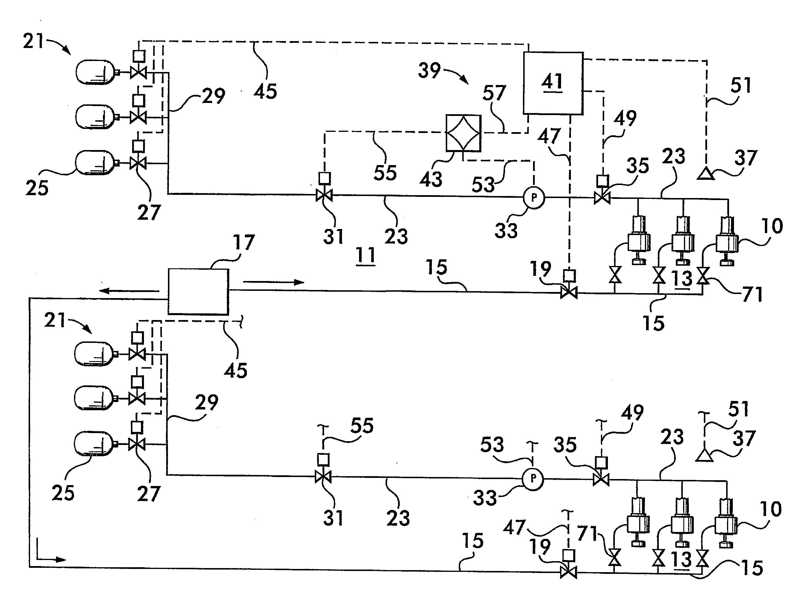
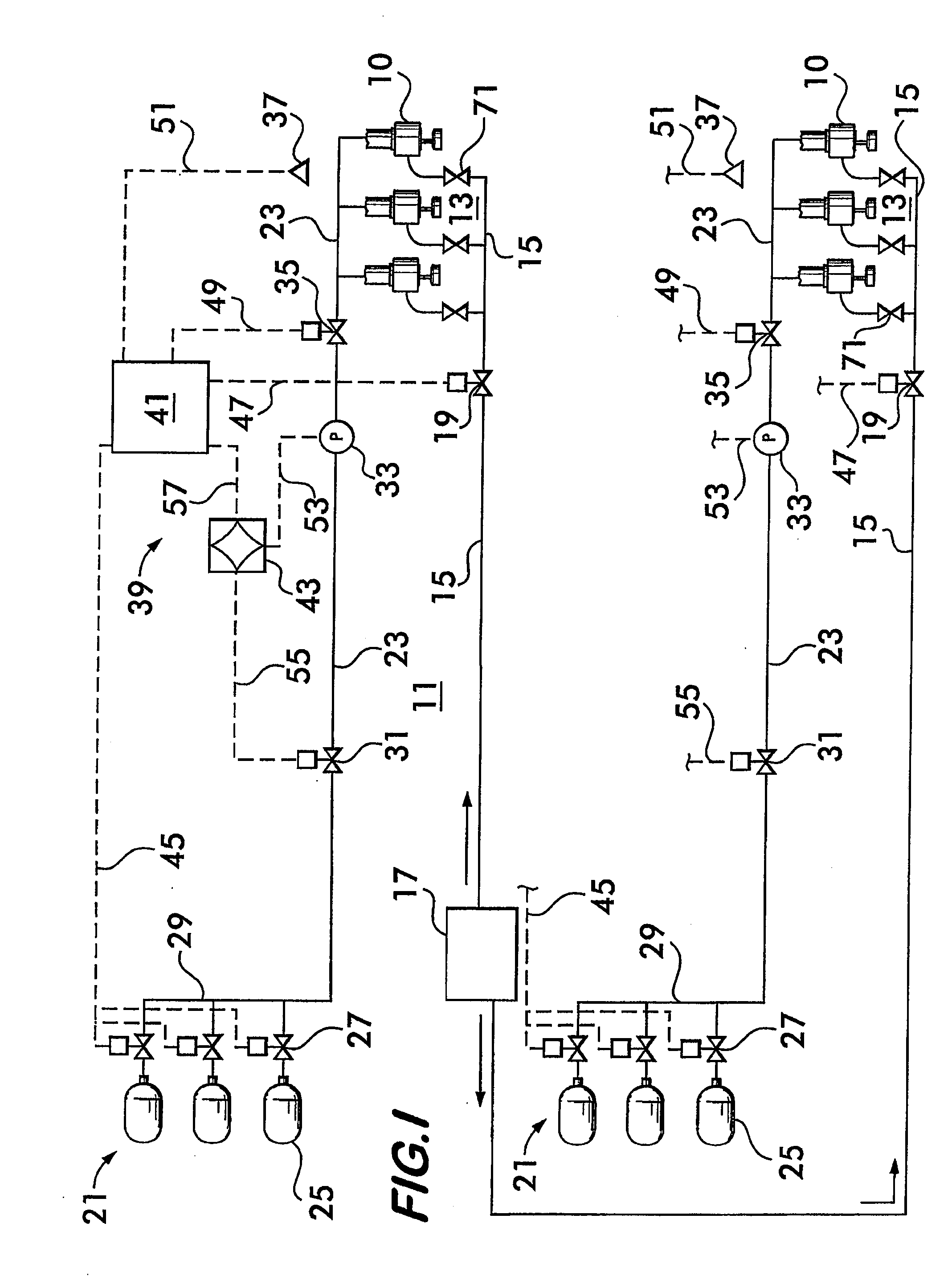
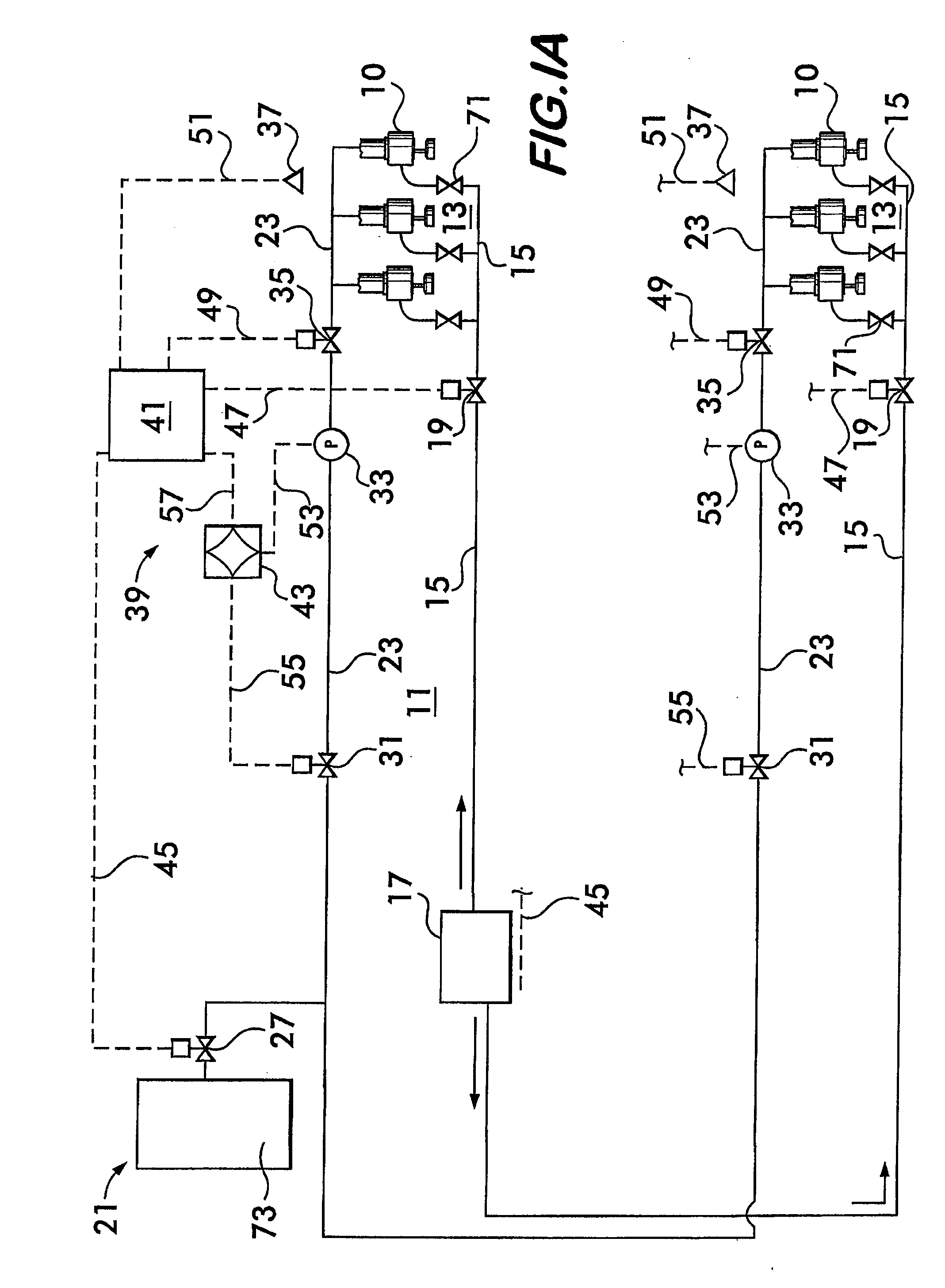
[0030]FIG. 1 illustrates, in schematic form, an example dual extinguishment fire suppression system 11 according to the invention. System 11 includes a plurality of high velocity low pressure emitters 10, described in detail below. Emitters 10 are arranged in a potential fire hazard zone 13, the system comprising one or more such zones, each zone having its own bank of emitters. For clarity, only one zone is described herein, it being understood that the description is applicable to additional fire hazard zones as shown.

[0031]The emitters 10 are connected via a piping network 15 to a source of pressurized liquid extinguishing agent 17. Examples of practical liquid agents include synthetic compounds such as heptafluoropropane (sold under the tradename Novec™ 1230), bromochloro-difluoromethane and bromotrifluoromethane. Water is also feasible, and especially de-ionized water for use near charged electrical equipment. De-ionized water reduces electrical arcing due to its low conductivi...


PUM


Abstract

A fire suppression system is disclosed. The system includes a gaseous extinguishing agent and a liquid extinguishing agent. At least one emitter is in fluid communication with the liquid and gas. The emitter is used to establish a gas stream, atomize and entrain the liquid into the gas stream and discharge the resulting liquid-gas stream onto the fire. A method of operating the system is also disclosed. The method includes establishing a gas stream having first and second shock fronts using the emitter, atomizing and entraining the liquid with the gas at one of the two shock fronts to form a liquid-gas stream, and discharging the stream onto the fire. The method also includes creating a plurality of shock diamonds in the liquid-gas stream discharged from the emitter.

Description

CROSS-REFERENCE TO RELATED APPLICATION[0001]This application is based on and claims priority to U.S. Provisional Application No. 60 / 864,480, filed Nov. 6, 2006.FIELD OF THE INVENTION [0002]This invention concerns fire suppression systems using devices for emitting two or more extinguishing agents in a flow stream projected away from the device onto a fire.BACKGROUND OF THE INVENTION[0003]Fire control and suppression sprinkler systems generally include a plurality of individual sprinkler heads which are usually ceiling mounted about the area to be protected. The sprinkler heads are normally maintained in a closed condition and include a thermally responsive sensing member to determine when a fire condition has occurred. Upon actuation of the thermally responsive member, the sprinkler head is opened, permitting pressurized water at each of the individual sprinkler heads to freely flow therethrough for extinguishing the fire. The individual sprinkler heads are spaced apart from each ot...

Claims


Application Information

Patent Timeline
Patent Type & Authority Applications(United States)
IPC IPC(8): A62C35/68
CPCA62C35/68B05B7/0853B05B1/265A62C37/36A62C35/58A62C37/40
Inventor REILLY, WILLIAM J.BALLARD, ROBERT J.BLEASE, KEVIN J.IDE, STEPHEN R.
Owner VICTAULIC
Why Eureka
Try Eureka