Non-uniform Image Defect Inspection Method
a defect inspection and non-uniform technology, applied in image enhancement, image analysis, instruments, etc., can solve the problems of high quality requirements, inability to easily detect human eyes and ccd (charge-coupled device) cameras, and inability to achieve the same qualities of inspected lcd products. to achieve the effect of improving inspection efficiency
- Summary
- Abstract
- Description
- Claims
- Application Information
AI Technical Summary
Benefits of technology
Problems solved by technology
Method used
Image
Examples
embodiment 1
Eliminating the Non-Uniform Background of the Original 2D Image
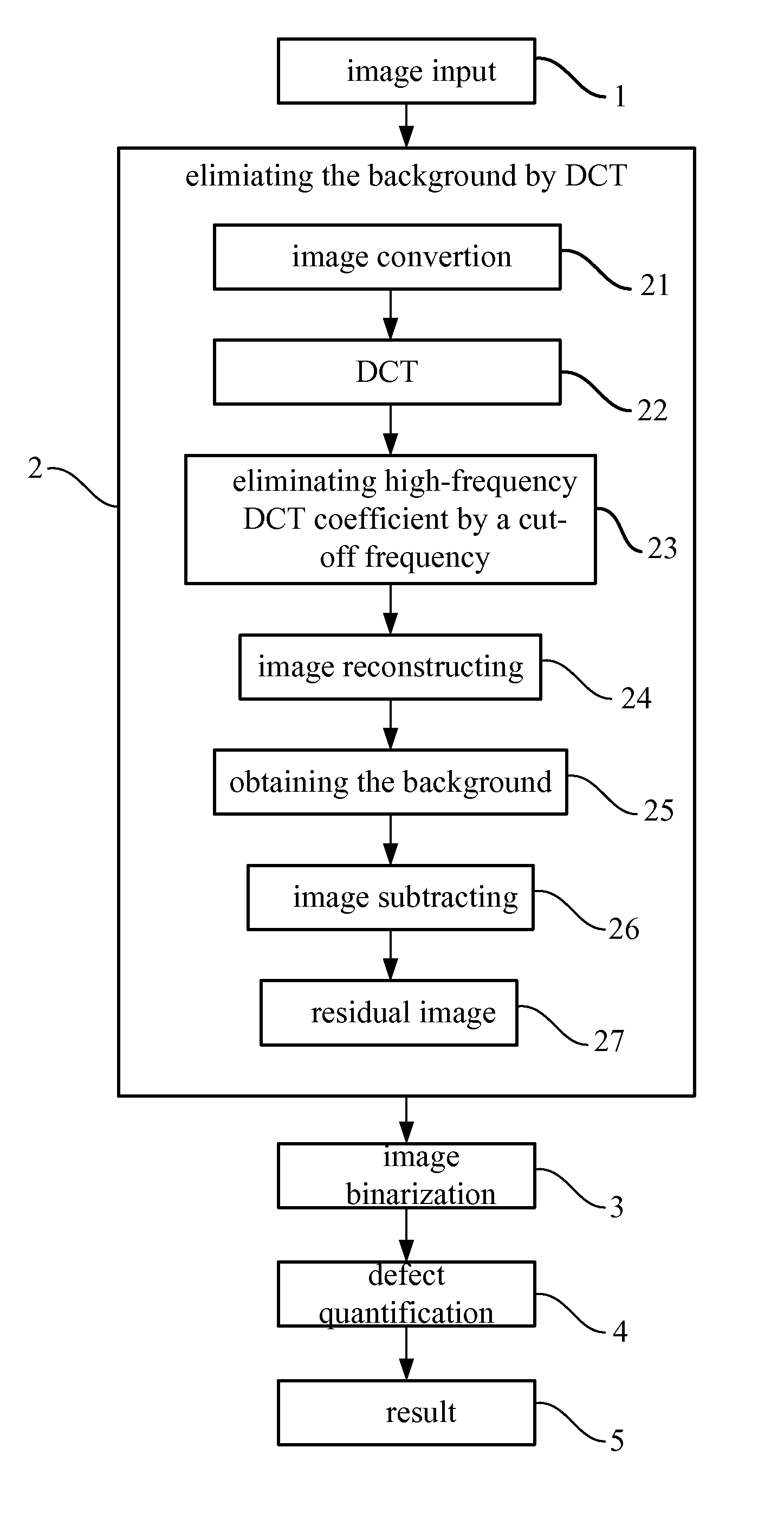
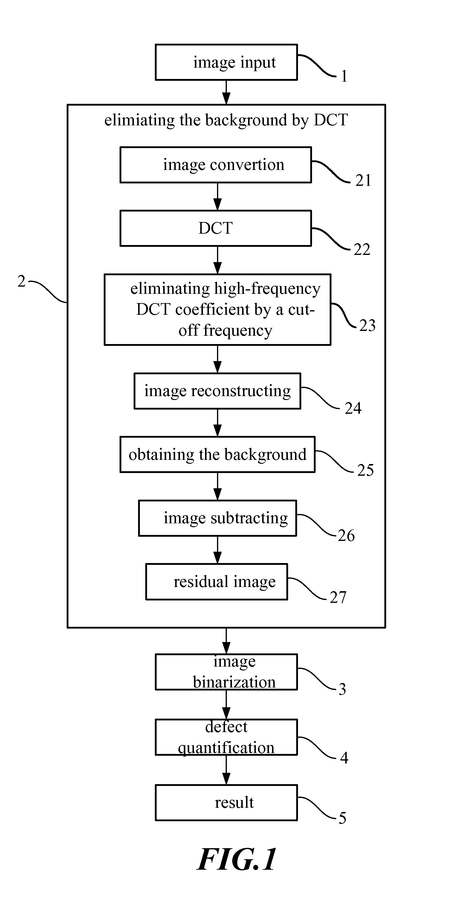
[0048] In the invention, the input image is converted from space domain to frequency domain by a 2D DCT which is defined as the formula 1: C(u,v)=α1(u)α2(v)∑x=0M-1 ∑y=0N-1 f(x,y)cos[π(2x+1)u2M]cos[π(2y+1)v2N](1)
[0049] Wherein the original image is denoted as M×N which can be adjusted according to a demanded resolution of the inspector;
[0050] f(x,y) denotes the input information;
[0051] C(u,v) denotes the output DCT coefficients; x=0,1,2,… ,M-1;y=0,1,2,… ,N-1;u=0,1,2,… ,M-1;v=0,1,2,… ,N-1;α1(u)={1M for u=02M for u≠0.α2(v)={1N for v=02N for v≠0.
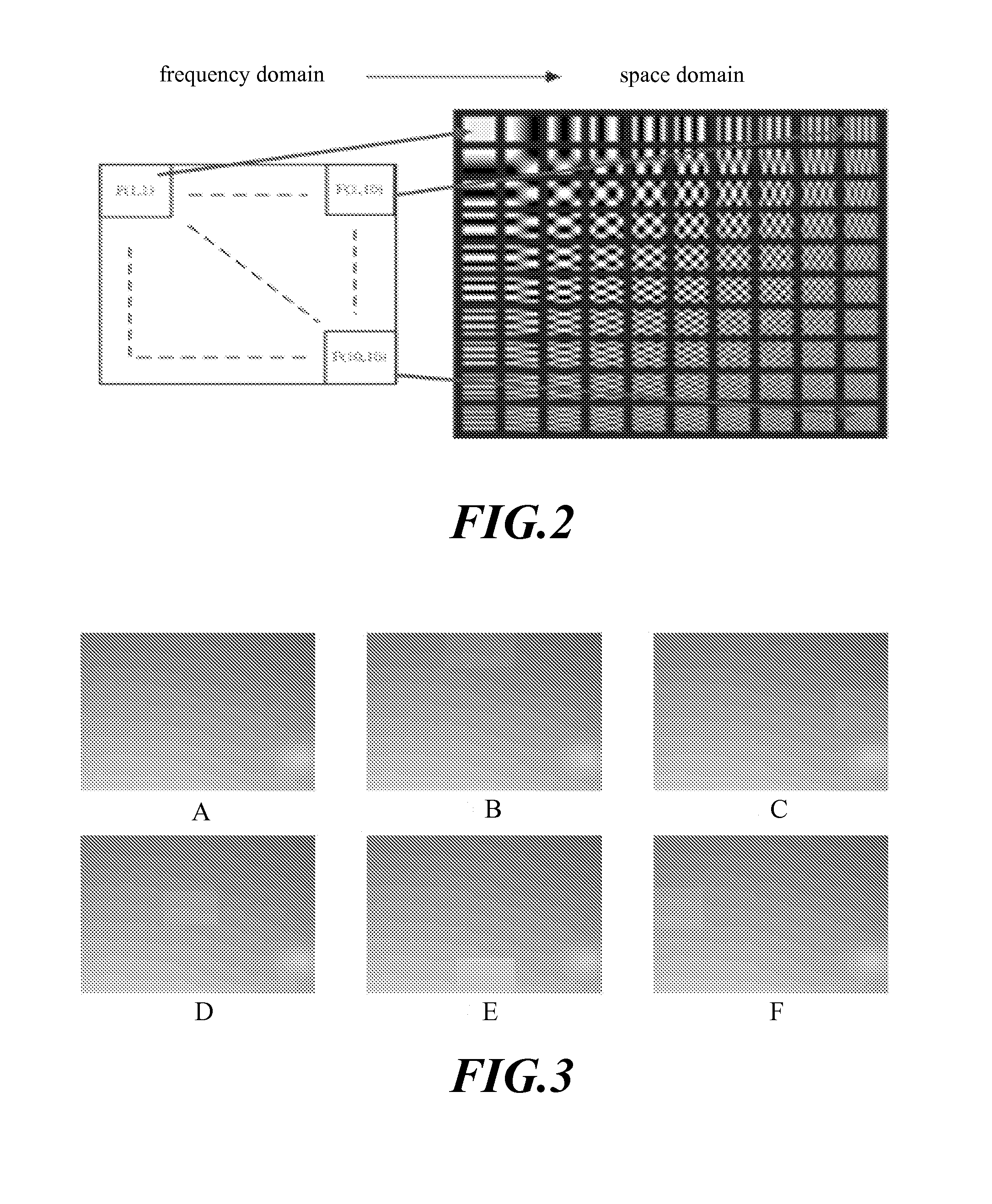
[0052] The 2D DCT describes an original image with a plurality of 2D fundamental image arrays. A 2D fundamental image array is a product of a vertical fundamental array and a horizontal fundamental array, as shown in formula 2. With different u or different v, a fundamental array image has different brightness. The bigger u or v ...
embodiment 2
Image Binarization
[0059] After reconstruction by DCT, the residual image is performed using an image binarization. In this embodiment, the image binarization is a maximum entropy method. The maximum entropy method is applied to obtain an optimal threshold that is utilized to segment defects from the background image. The image regions whose brightness is higher than the optimal threshold are defined as defect regions, and the image regions whose brightness is lower than the optimal threshold are defined as background regions. Then a gray value of the defect is set to 255, and a gray value of the background is set to 0. In addition, any other binarization operation can be used as the image binarization.
[0060] According to the second law of thermodynamics, when a system is on a uniform disorder state, the entropy of the system is the maximum. As a function, the entropy is utilized to denote the disorder grade of a system. If the incident probability is average distributed, the entro...
embodiment 3
[0063] The image performed an image binarization may include some non-uniform regions. To segment each individual non-uniform image defect region, an image segmentation is performed and each individual non-uniform image defect region is labeled with a unique codeword. In this embodiment, each pixel is regarded as a seed, and image segmentation is performed by searching pixel to pixel from the original pixel on the left corner, by way of that from left to right and from top to bottom. FIG. 5 shows the procedure of the image segmentation. Assuming that the gray value of the dark points in the binarization image is 0, and the gray value of the bright points (defects) is 255. The procedure is started by searching for a first bright point which is regarded as a seed (shown in FIG. 5A). Then, label the seed with a codeword A, and perform a region growing operation based on four neighbors or eight neighbors to search pixels that are bright points and connected with the s...
PUM
 Abstract
Description
Claims
Application Information
 - R&D
- Intellectual Property
- Life Sciences
- Materials
- Tech Scout
- Unparalleled Data Quality
- Higher Quality Content
- 60% Fewer Hallucinations
Browse by: Latest US Patents, China's latest patents, Technical Efficacy Thesaurus, Application Domain, Technology Topic, Popular Technical Reports.
© 2025 PatSnap. All rights reserved.Legal|Privacy policy|Modern Slavery Act Transparency Statement|Sitemap|About US| Contact US: help@patsnap.com


