Rolling Device

a rolling device and rolling plate technology, applied in mechanical equipment, lighting applications, lighting, etc., can solve the problems of insufficient lubricity, insufficient life of the rolling device, and risk of reducing the effect of the oil reservoir, so as to prolong the effect of lubricant film, prolong the life, and improve the adhesion

Inactive Publication Date: 2008-05-08
NSK LTD
View PDF13 Cites 30 Cited by
  • Summary
  • Abstract
  • Description
  • Claims
  • Application Information

AI Technical Summary

Benefits of technology

[0032]According to this configuration, since the solid lubricant is filled in the dimples to improve the adherence between the section on which the lubricant film was coated and the lubricant film, the rolling device will have a longer life in comparison to a case without dimples. Further, since the solid lubricant is trapped inside the dimples when the rolling device is driven, the effect of the lubricant film is maintained longer. In order to obtain this effect, it is necessary to make the depth of the dimples no less than 0.1 μm. Since no additional effect can be anticipated even if the depth of the dimples exceeds 5 μm, the depth of the dimples is preferably made no more than 5 μm. In order to make this effect even more reliable, the dimple depth is more preferably made no less than 0.2 μm and no more than 3 μm, and further preferably no less than 0.5 μm and no more than 3 μm. Dimples may also be formed on the surface of the lubricant film in the same manner as described above.
[0033]The center line average roughness Ra of the surface of the lubricant film is preferably no more than 1 μm. According to this configuration, as well as a long life, the acoustic characteristics of the rolling device are also favorable. If the center line average roughness Ra exceeds 1 μm, the lubrication conditions become severe and surface origin shot flaking may occur. To make it more difficult for this disadvantage to occur, the enter line average roughness Ra is preferably no more than 0.5 μm. Although the lower limit value of the center line average roughness Ra is not particularly limited, a value of 0.1 μm or more is preferable. If the lower limit value is less than 0.1 μm there is a risk that the oil reservoir effect will be decreased by minute asperities. In this connection, the ability to form a lubricant film does not noticeably decrease even when the center line average roughness Ra is a value as described above.
[0034]The solid lubricant is preferably at least one kind of lubricant among the group consisting of molybdenum disulfide, tin and copper. In particular, tin is preferable when forming a lubricant film on a rolling section. In this case, the purity of tin is preferably 95% or more, and more preferably 98% or more. When the purity is 95% or more, it is easy to obtain an even lubricant film. According to this arrangement, an effect is obtained that improves at least one member of the group consisting of smearing, seizure, abrasion, peeling and the like at a rolling section in particular.

Problems solved by technology

If the area ratio of the section on which the lubricant film is coated is less than 75%, there is a risk that the life of the rolling device will be insufficient.
Also, if the area ratio of the section on which the lubricant film is coated exceeds 95%, there is a risk that the oil reservoir effect will decrease somewhat.
If the thickness of the lubricant film is less than 0.05 μm there is a risk that the lubricity will be insufficient.
If the lubricant film thickness exceeds 8 μm there is a risk that the strength of the lubricant film will be insufficient.

Method used


Image

  • Rolling Device
  • Rolling Device
  • Rolling Device

Examples


first embodiment

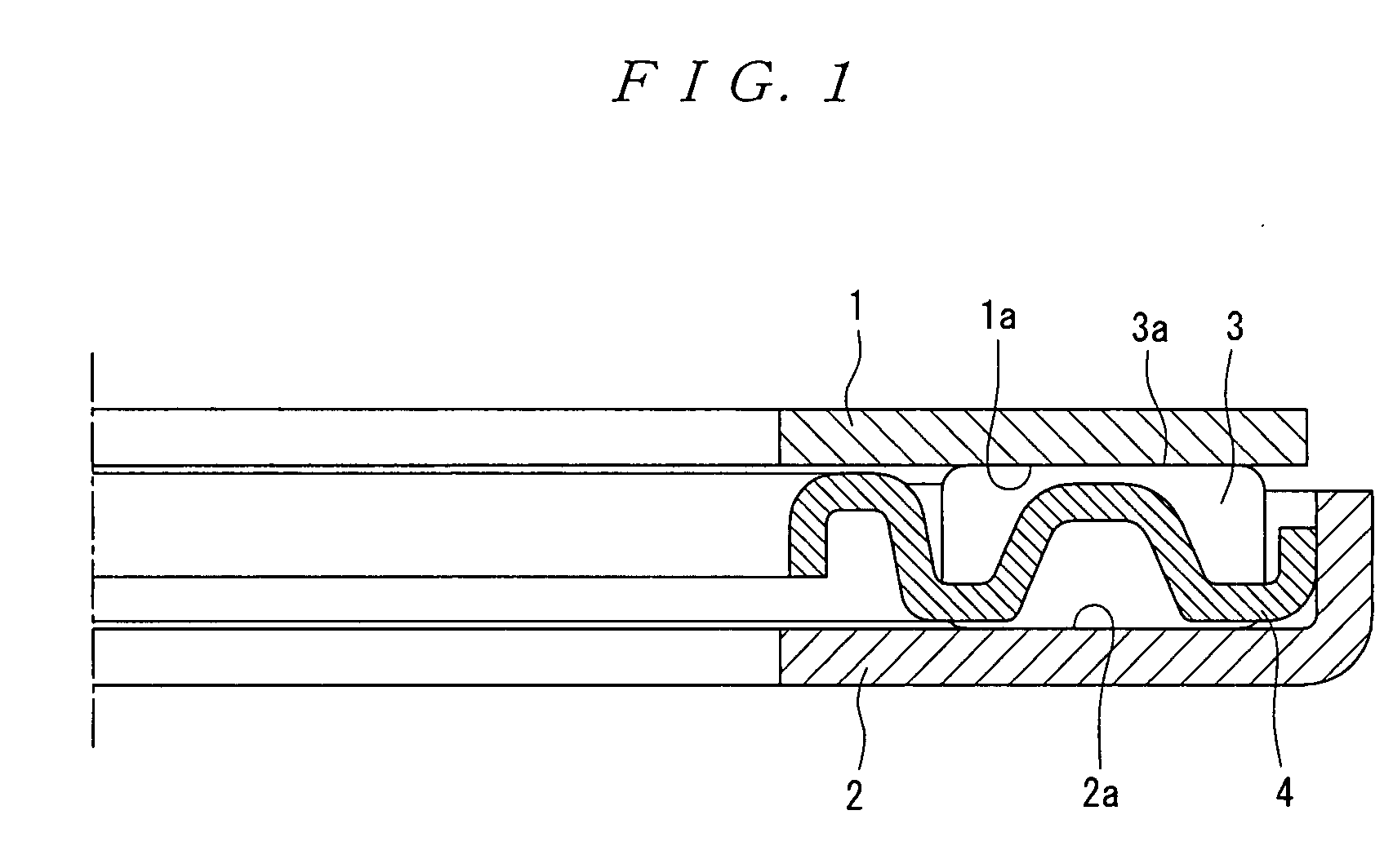
[0075]FIG. 1 is a partial longitudinal section showing the configuration of a thrust needle roller bearing as a first embodiment of a rolling device according to the present invention.

[0076]The thrust needle roller bearing shown in FIG. 1 comprises an inner ring 1 (inner member) that is fixed to an unshown shaft; an outer ring 2 (outer member) that is fixed to an unshown housing; a plurality of rolling elements 3 that are rollably disposed between a raceway surface 1a of the inner ring 1 and a raceway surface 2a of the outer ring 2; and a cage 4 that retains the plurality of rolling elements 3 between the two rings 1 and 2.

[0077]A lubricant film (not shown) comprising a solid lubricant is coated on a section that is equivalent to an area ratio of not less than 75% of at least one member of the group consisting of the raceway surface 1a of the inner ring, the raceway surface 2a of the outer ring 2, and a rolling contact surface 3a of the rolling element 3. Preferably, the thickness o...

second embodiment

[0111]Preferably, a lubricant film according to the present invention is formed by a shot peening method that accelerates a shot material using an inert gas or an active gas. As an inert gas, one kind or a combination of two or more kinds selected from the group consisting of N2 gas, He gas, Ne gas, Ar gas, Xe gas and Kr gas can be used. Further, one kind or a combination of two or more kinds selected from the group consisting of CF4 gas, S2F6 gas, NH3 gas, CH4 gas, C2H6 gas, C3H6 gas, C4H10 gas, C5H12 gas, RX gas, O2 gas, H2 gas and the like can also be used.

[0112]Since it is thus possible to activate the surface of a rolling component with which shot material collided, adherence between the surface and the lubricant film can be enhanced in comparison to the case of accelerating the shot material using atmospheric gas. In particular, by using N2 gas or NH3 gas that forms a nitrided layer on the surface of the rolling component, or CH4 gas, C2H6 gas, C3H6 gas, C4H10 gas, C5H12 gas o...

third embodiment

C of Third Embodiment

[0190]FIG. 8 is a cross section of a deep groove ball bearing 203 according to C of the third embodiment. This deep groove ball bearing 203 can be used, for example, in place of the thrust bearing 238 that is provided on the left side of the drive shaft 222 in FIG. 7.

[0191]As shown in FIG. 8, the deep groove ball bearing 203 according to this embodiment comprises an inner ring 240 that is attachable to the drive shaft 222 shown in FIG. 7, an outer ring 42 that is attachable to the housing 220 shown in FIG. 7, a ball 244 as a rolling element that is rollably disposed between these inner and outer rings 240 and 242 as driving wheels, and a cage 246 that retains a plurality of the balls 244 in a manner whereby they are spaced at regular intervals in the circumferential direction.

[0192]Although the cage 246 is formed by bending and combining two steel plates, the same effect can be obtained by forming the cage with a resin.

[0193]The same treatment as that of the thr...


PUM


Abstract

A rolling device in which damage such as seizure or wear is less liable to occur and which has a long life, even when used under severe conditions such as high speed, heavy load, high temperature and insufficient lubrication. A thrust needle roller bearing includes an inner ring 1, outer ring 2, and a plurality of rolling elements 3 rollably arranged between a raceway surface 1a of inner ring 1 and a raceway surface 2a of outer ring 2. A lubricant film consisting of a solid lubricant is coated over an area equivalent to an area ratio of 75% or more of at least one member of the group consisting of raceway surface 1a of inner ring 1, raceway surface 2a of outer ring 2, and a rolling contact surface 3a of rolling element 3. The thickness of the lubricant film is preferably 0.05 μm or more and 8 μm or less.

Description

TECHNICAL FIELD[0001]The present invention relates to a rolling device such as a rolling bearing, a linear guide device, a ball screw and a linear motion bearing.BACKGROUND ART[0002]Generally, in a rolling device such as a rolling bearing, a rolling movement is performed between a rolling element, an outer member and an inner member that constitute a rolling device, and the raceway surfaces of the inner member and the outer member as well as the rolling contact surface of the rolling element receive repeated contact stress. Therefore, the properties required of a material constituting the inner member, outer member and rolling element include hardness, load endurance, a long rolling fatigue life, and favorable wear resistance with respective to sliding.[0003]Thus, as the material constituting these members, SUJ2 according to the Japanese Industrial Standards is generally used as bearing steel, SUS440C according to the Japanese Industrial Standards or 13Cr martensitic stainless steel...

Claims


Application Information

Patent Timeline
Patent Type & Authority Applications(United States)
IPC IPC(8): F16C19/00
CPCF16C19/30F16C2202/54F16C33/34F16C33/565F16C33/62F16C33/6696F16H25/20F16H2025/249F16C19/06F16C19/364F16C33/366F16C33/425F16C33/585Y10S384/907F16C2204/34F16C33/32F16C2362/52F16C2360/22F16C2240/44F16C2360/00F16C2240/60F16C2240/40
Inventor FUJITA, SHINJIUCHIDA, HIROYUKIMURAKAMI, YASUOHACHIYA, KOICHITAKAHASHI, DAIJU
Owner NSK LTD
Why Eureka
Try Eureka