Injectable hollow tissue filler

a filler and hollow tissue technology, applied in the field of new injectable hollow tissue fillers, can solve the problems of loss of skin volume, uneven skin surface, ulcers in other organs, etc., and achieve the effect of low viscosity and low viscosity

Inactive Publication Date: 2008-05-08
CHU JACK FA DE
View PDF31 Cites 102 Cited by
  • Summary
  • Abstract
  • Description
  • Claims
  • Application Information

AI Technical Summary

Benefits of technology

[0016]The hollow particulate filler is free of sharp corner or edge. It can be spherical, elliptic, oval, etc. with a smooth non-porous outer surface to avoid inflammation or other adverse body reaction. The average cross sectional dimension ranges from about 20 μm to about 500 μm, preferably, from about 30 μm to about 200 μm. The particulate filler is able to secure itself into the injection position through the large particle size which can not be engulfed by the macrophages in the body. Aggregation and injection difficulty can be minimized by the lower density and the smooth non-tacky particulate surface. After the injection, pluralities of hollow particles in the composition occupy a predetermined volume when the carrier is slowly removed from the body. According to the present invention, the hollow particles have a lower effective density comparable to carrier and are evenly distributed in the body without clumping. Because this homogenous suspension of hollow particles is not affected by the change in viscosity during the resorption of carrier in the body, the hollow particles remain evenly distributed in the body without causing palpable masses at the injection sites.
[0018]According to the present invention, the carrier mixed with hollow particles can possess a low viscosity without causing precipitation. The biologically compatible carrier cause minimal tissue reaction and is removable or metabolized in the body. Due to this relatively lower viscosity, a larger volume of hollow particles can be used in the composition without injection difficulty or clumping. The hollow particulate fillers are typically present in a concentration from about 10%-80% of total volume of the composition, more typically from about 20% to about 60%. The amount of hollow fillers in the composition varies according to the size of the injection needle and the location of treatment.

Problems solved by technology

This loss in skin volume creates uneven skin surface such as wrinkles, laugh lines, folds and furrows on the face.
However, their effect is temporary because the body eventually breaks down the filler.
However, some bacterial infections within the gel have been reported in the literature.
In addition, the low molecular weight silicone in the gel can slowly migrate into patients' system and cause problem such as nodules, cellulites, and ulcers in other organs.
As a result, bacterial infection and migration are major concerns for liquid permanent fillers.
However, limited success has been reported in some of these approaches.
The clinical results were mostly disappointing due to acute or chronic adverse tissue reactions, clumping of particles, injection difficulty, and filler migration to other locations.
However, large particles tend to clump and form aggregation in the syringe and inhibit injection.
However, the solid beads are relatively heavy.
However, hydrogel is lubricious and known not to adhere to the surrounding tissue, migration of this material to other organs (such as brain tissue) is still a concern.
However, the high viscosities fluids increase injection difficulty and the chance for adverse incidences.
With this approach, the average particles size has to be in a delicate balance between too small (the risk of being engulfed by macrophages and lead to migration) and too big (injection difficulty).

Method used


Image

  • Injectable hollow tissue filler
  • Injectable hollow tissue filler
  • Injectable hollow tissue filler

Examples


Embodiment Construction

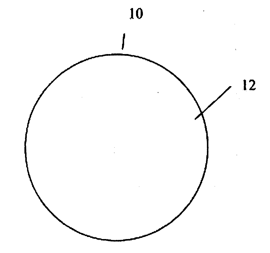
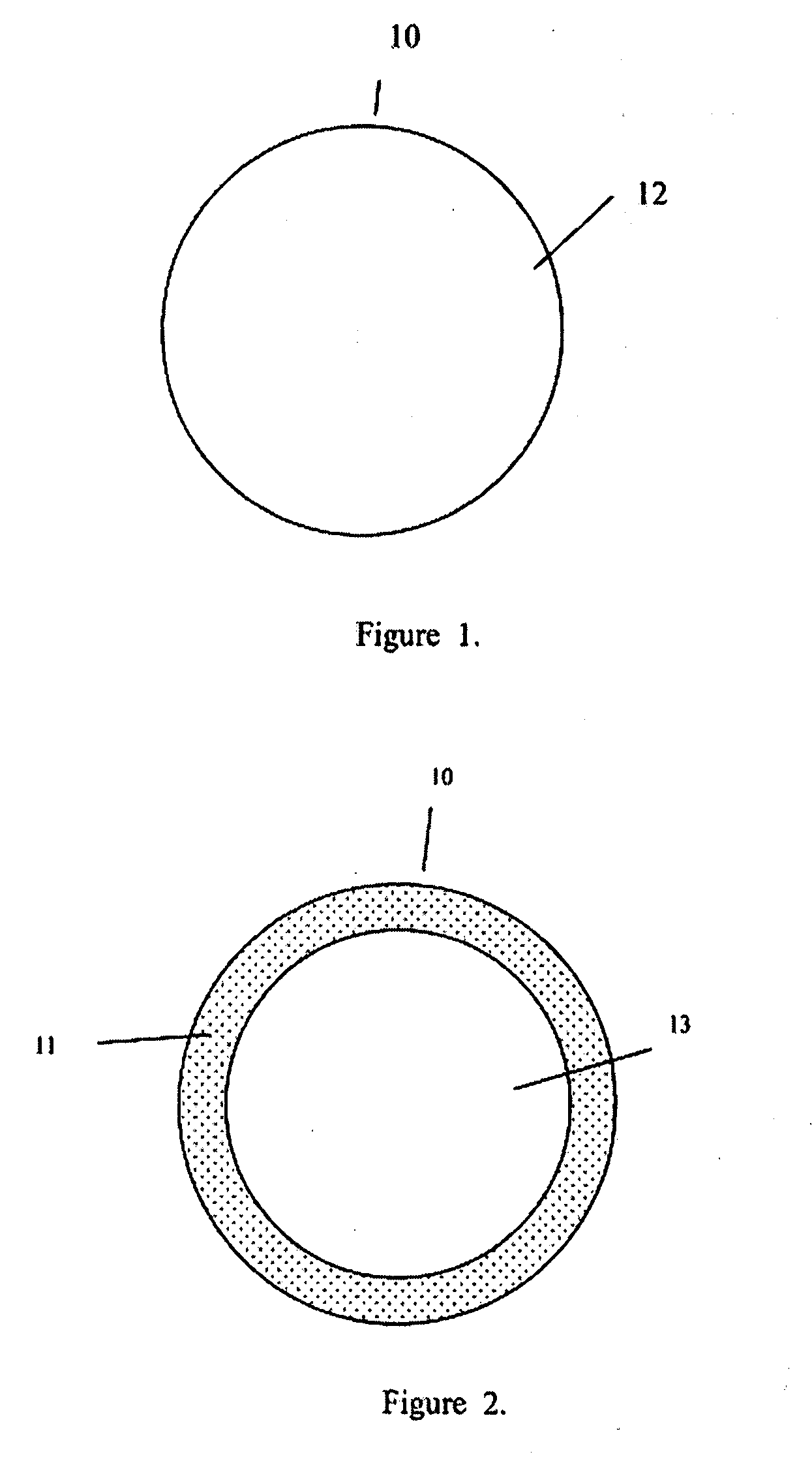
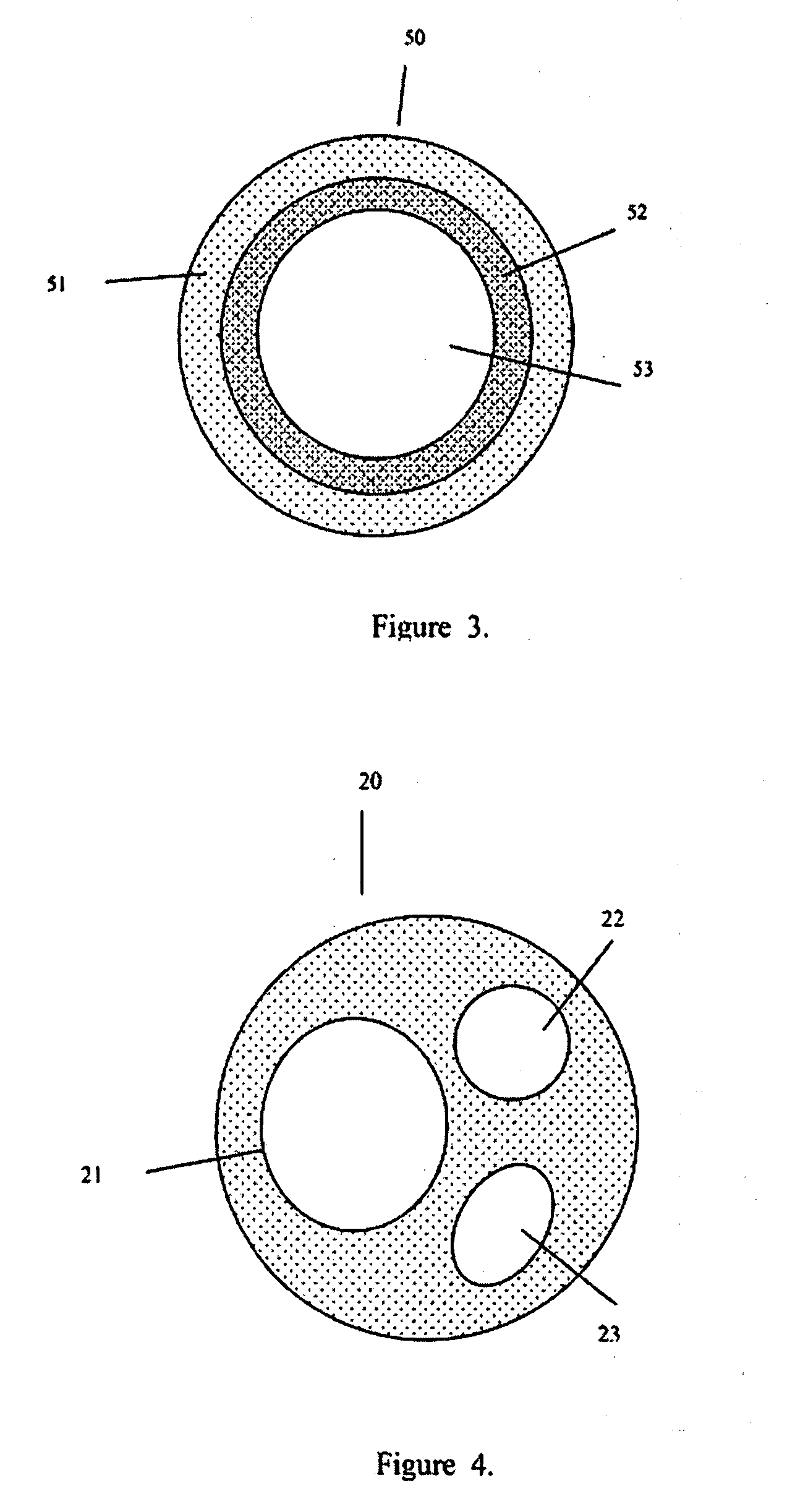
[0029]The present invention addresses those aspects of designing an ideal filler composition for tissues that need to be repaired, augmented or strengthened. Other than the treatment of lost skin volume by plastic or reconstructive surgery, tissue fillers can be used to correct aphonia or dysphonia caused by paralysis of the vocal cords, to correct defect or injury, to the augmentation of hypoplastic breast, to the augmentation of scar tissue, to the treatment of urological disorders (e.g. urinary incontinence), to the treatment of incompetent anal sphincters, to the treatment of vesicoureteral reflux, and to the treatment of gastric fluid reflux by endoscopical or subcutaneous injection of biocompatible hollow particulate fillers into the submucosal or dermal tissue. Since the invention is closely related to the augmentation of soft tissue for the treatment of lost skin volume, it will be described in details hereto.

[0030]It is typical for injectable particulate fillers to be suspe...


PUM


Abstract

The present invention comprises a plurality of injectable hollow particulate fillers suspended in a biocompatible fluid carrier to significantly improve the clumping resistance and injectability of the composition. The hollow particulate fillers have a lower effective density and are able to suspend in the carrier without precipitation. The loss of skin volume as a result of aging, diseases, weight loss, and injury can lead to uneven skin surface (e.g. wrinkle, etc.). The uneven skin can be repaired by injecting appropriate amount of hollow fillers underneath the skin. Some cases of urinary incontinence occur when the resistance to urine flow has decreased excessively. Continence is restored by injecting the present invention to the urethra tissue to increase resistance to urine outflow. Similarly, the present invention allows for the control of gastric fluid reflux by submucosal injections of the fillers to the esophageal-gastric and gastric-pyloric junction. For patients with vesicoureteral reflux, it can be treated by injection of the present invention into patients' ureteral tissue. This invention can also be used to repair defective or inadequately functioning muscles of the anal sphincter by administering an effective amount of injectable hollow fillers into the defect or anal sinuses.

Description

[0001]This application claims the benefit of U.S. Provisional Application No. 60 / 864,446, which was filed Nov. 6, 2006, the disclosure of which is incorporated herein by this reference.FIELD OF INVENTION[0002]The present invention is about a new injectable hollow particulate filler used to the repair of defect or injury, to the augmentation of soft tissue, to the augmentation of a hypoplastic breast, to the augmentation of scar tissue, to the treatment of urological disorders, to the treatment of incompetent anal sphincters, to the treatment of paralysis of the vocal cords, to the treatment of vesicoureteral reflux, and to the treatment of gastric fluid reflux by endoscopical or subcutaneous injection of biocompatible hollow particular implants into the submucosal or dermal tissue.BACKGROUND OF THE INVENTION[0003]The present invention addresses those aspects of designing an ideal composition for tissues that need to be repaired. The injectable composition of this invention is also s...

Claims


Application Information

Patent Timeline
Patent Type & Authority Applications(United States)
IPC IPC(8): A61K9/14A61F2/02
CPCA61F2/0036A61F2/105A61K9/0024A61L2400/06A61K9/0034A61L27/56A61K9/0031A61P17/00
Inventor CHU, JACK FA-DE
Owner CHU JACK FA DE
Why Eureka
Try Eureka