High-capacity, low-leakage multilayer dielectric stacks

a multi-layer dielectric, high-capacity technology, applied in the direction of synthetic resin layered products, natural mineral layered products, chemistry apparatuses and processes, etc., can solve the problems of limited scaling of devices, limited research requirements, and few materials promising with respect to all of these guidelines

Inactive Publication Date: 2008-05-08
UNIV OF CONNECTICUT
View PDF2 Cites 41 Cited by
  • Summary
  • Abstract
  • Description
  • Claims
  • Application Information

AI Technical Summary

Benefits of technology

[0011] The present disclosure provides for exemplary systems, devices, assemblies and methods for designing a high capacity low-leakage stack including a multilayer stack having at least a first dielectric layer defining a thickness parameter h2 coupled with at least a first ferroelectric layer defining a thickness parameter h1. The dielectric layer includes a dielectric material and the ferroelectric layer includes a ferroelectric layer. The multilayer stack defines a thickness parameter h such that h=h1+h2. An exemplary method according to the present disclosure includes the steps of selecting a dielectric material having a dielectric constant and designing a stack by correlating the dielectric constant with a critical fraction α. The critical fraction α is determined by the expression α=h2 / h.

Problems solved by technology

However, these plans are typically 3-4-year near-term solutions to address issues and ultimately post a limitation on scaling a device.
Many dielectrics appear favorable in some of these areas, but very few materials are promising with respect to all of these guidelines.
While work is ongoing, much research is still required, as it is clear that any material which is to replace SiO2 as the gate dielectric faces a formidable challenge.
The requirements for process integration compatibility are remarkably demanding, and any serious candidates will emerge only through continued, intensive investigation.
However, they fail to disclose a method of designing and scaling a stack for implementation to relevant applications.
A further limitation alleviated by the present disclosure is increased leakage and loss due to scaling and improper polarization of the conductive materials.

Method used


Image

  • High-capacity, low-leakage multilayer dielectric stacks
  • High-capacity, low-leakage multilayer dielectric stacks
  • High-capacity, low-leakage multilayer dielectric stacks

Examples


example 1

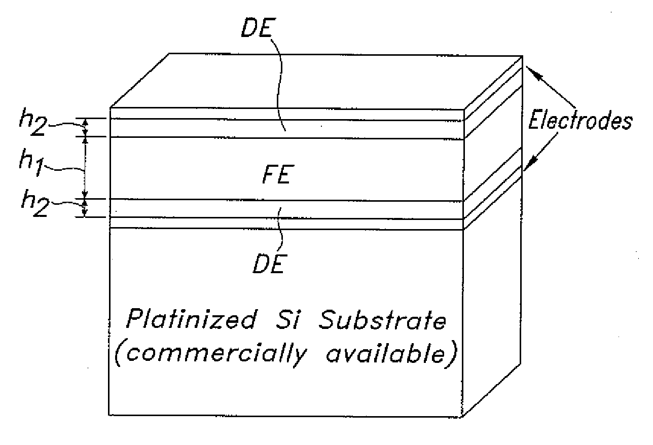
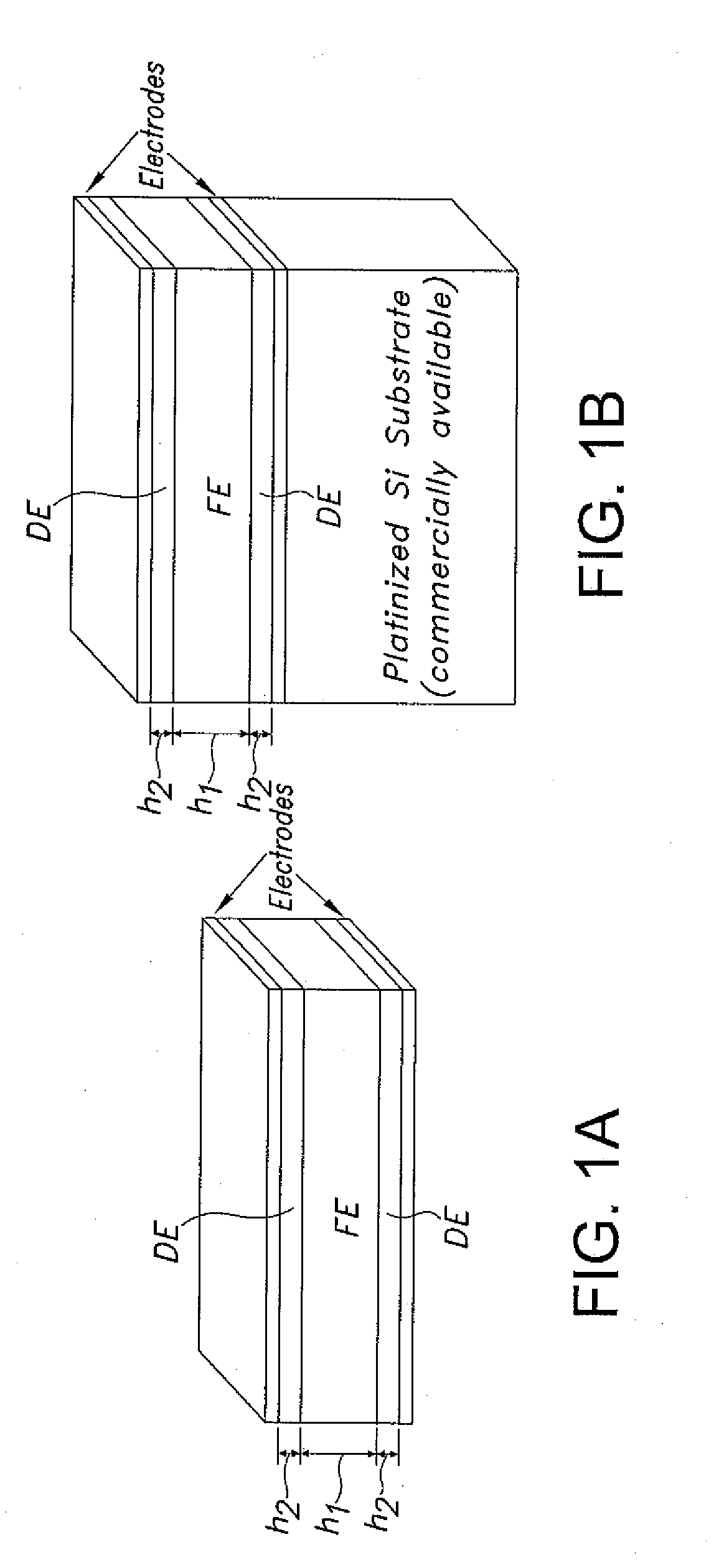
[0047] The present disclosure relates to a thermodynamic model that at least in pertinent part describes the polarization and the dielectric response of ferroelectric-paraelectric bilayers and multilayers. Paraelectric layers can be dielectric materials. A strong electrostatic coupling between the layers typically results in the suppression of ferroelectricity at a critical paraelectric layer thickness. The bilayer is expected to have a gigantic dielectric response similar to the dielectric anomaly near Curie-Weiss temperature in homogeneous ferroelectrics at the determined critical thickness. A numerical analysis is carried out for a pseudomorphic BaTiO3 / SrTiO3 heteroepitaxial bilayer on SrTiO3 and a stress-free BaTiO3 / SrTiO3 bilayer. Complete polarization suppression and a dielectric peak are predicted to occur at approximately 66% and 14% of SrTiO3 in these two systems, respectively.

[0048] Ferroelectric (FE) multilayers, superlattices, and graded ferroelectrics have attracted co...

example 2

[0067] Compositional variations across ferroelectric bilayers result in broken spatial inversion symmetry that can lead to asymmetric thermodynamic potentials. For the case of insulating materials, ferroelectric multilayers will self-pole due to the electrostatic coupling between the layers. Polarization-graded ferroelectrics with smooth composition, temperature, or stress gradients are viewed as bilayer structures in the limit of the ever-increasing number of bilayer couples, thus concluding that the unconventional hysteresis associated with “up” and “down” polarization graded structures are real phenomena, and not artifacts associated with free charge or asymmetric leakage current.

[0068] Significant time has passed since an unconventional form of hysteresis was first observed and characterized from polarization-graded ferroelectrics (FE's). Subsequently, it was concluded that the offsets observed from “up” and “down” graded materials were the result of “built-in” potentials due t...


PUM

PropertyMeasurementUnit
dielectric constantaaaaaaaaaa

Abstract

The present disclosure is directed to an exemplary method for designing, implementing, and making a high capacity low leakage multilayer stack for various electronic applications. In a particular embodiment, the multilayer stack is made up of a dielectric/ferroelectric/dielectric trilayer. This configuration has shown to have giant dielectric permittivity which is much higher than conventional gate dielectrics. The DE/FE interlayer exhibits strong interlayer coupling, yielding desired properties. In order to prevent leakage and loss while maintaining high capacity, certain parameters of each layer must exist. The present disclosure describes a method of quantitatively achieving these parameters through correlating critical fraction with dielectric constant. Moreover, this method can be used for scalability of electronic materials.

Description

CROSS-REFERENCE TO RELATED APPLICATIONS [0001] The present application claims the benefit under 35 U.S.C. § 119(e) of U.S. Provisional Application No. 60 / 830,306, filed Jul. 12, 2006. The foregoing application is also hereby incorporated by reference in its entirety for all purposes.BACKGROUND [0002] 1. Technical Field [0003] The present disclosure relates to systems and methods for designing, implementing, and making multilayer dielectric stacks for use in integrated circuit (IC) devices. [0004] 2. Background Art [0005] The semiconductor industry trend is to scale down the size of devices while still improving performance, including good figures of merit (FOM) and low energy consumption. For example, the current solutions for dielectric gate materials of complementary metal-oxide-semiconductor (CMOS) transistors are to utilize Si3N4, SiOxNy, and Si—N / SiO2 dielectrics, according to the most recent industry roadmaps. However, these plans are typically 3-4-year near-term solutions to ...

Claims


Application Information

Patent Timeline
Patent Type & Authority Applications(United States)
IPC IPC(8): B32B9/00H01L21/00
CPCH01L28/56
Inventor ALPAY, S. PAMIRMANTESE, JOSPEH V.ZHONG, SHAN
Owner UNIV OF CONNECTICUT
Why Eureka
Try Eureka