Microchip and Method for Detecting Molecules and Molecular Interactions

a molecular interaction and microchip technology, applied in the field of detection of molecules and molecular interactions, can solve the problems of false or inaccurate detection, cross-interference between different test sites, and disadvantages of conventional microchips, and achieve the effect of inhibiting the diffusion of molecules

Active Publication Date: 2008-05-08
NANYANG TECH UNIV
View PDF11 Cites 9 Cited by
  • Summary
  • Abstract
  • Description
  • Claims
  • Application Information

AI Technical Summary

Benefits of technology

[0012]Another aspect of the present invention relates to a method of detecting molecules or molecular interaction. In this method, a microchip is provided. The microchip has a substrate, an inlet channel in the substrate, an outlet channel in the substrate, a plurality of test channels in the substrate each having an inlet for fluid communication with the inlet channel and an outlet for fluid communication with the outlet channel. The inlet is elevated from the outlet. One test site is in each one of the plurality of test channels. A fluid is introduced to the test channels through the inlet channel. Back flow through the inlets and outlets is inhibited by allowing overflow of the fluid from the test channels to the outlet channel through the outlets and maintaining the fluid level in the outlet channel below the outlets, thus inhibiting diffusion of molecules in the fluid from one of the test sites to another one of the test sites. After the fluid has been introduced to the test channels, a molecule or molecular interaction is detected at a test site within the plurality of test sites.

Problems solved by technology

However, conventional microchips suffer certain drawbacks.
For example, in known devices the test sites are often immersed in liquid during detection and cross-interference between different test sites can occur due to diffusion of the molecules to be detected from one test site to another.
Such cross-interference can lead to false or inaccurate detection results.
However, such an approach also has some drawbacks.
One problem is that only a small number of test sites can be formed on a microchip device when the distance between adjacent electrodes is so large.
However, these well-based microchips have their own limitations.
One problem is that well-density is limited, due to either manufacturing or operation requirements, so that it is difficult to form high-density test sites.
Another problem is that a well-based microchip does not allow flow-through operation, thus making automated operation difficult.
For example, automated sampling, washing, or dilution on such a chip may require expensive equipments such as robotic devices.

Method used


Image

  • Microchip and Method for Detecting Molecules and Molecular Interactions
  • Microchip and Method for Detecting Molecules and Molecular Interactions
  • Microchip and Method for Detecting Molecules and Molecular Interactions

Examples


Embodiment Construction

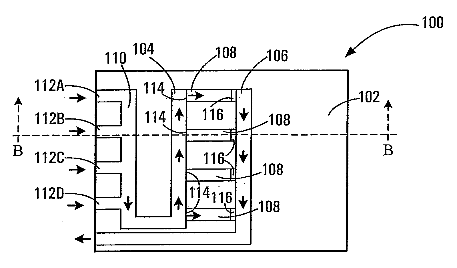
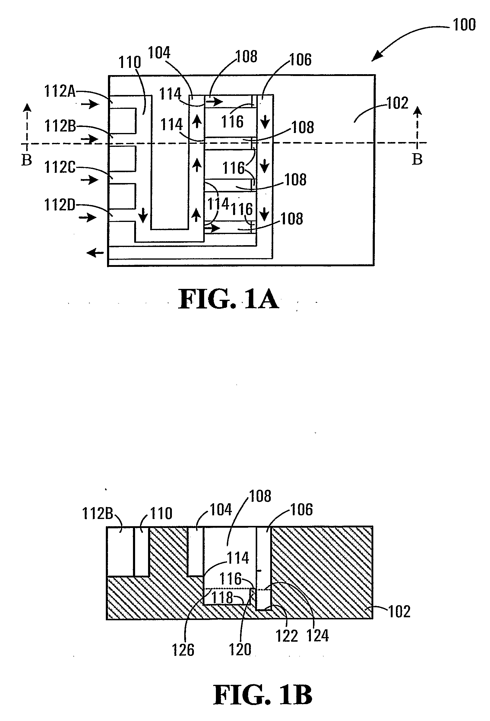
[0026]FIGS. 1A and 1B illustrate a microchip or microfluidic biochip 100, exemplary of an embodiment of the present invention.

[0027]Biochip 100 includes a substrate 102. An inlet channel 104, an outlet channel 106, and a plurality of test channels 108 are formed in substrate 102. The test channels 108 may be substantially parallel to each other. Inlet channel 104 is in fluid communication with, and can receive fluid from, a dilution channel 110. Dilution channel 110 has multiple inlets 112A to 112D (also collectively and individually referred to as 112), each for introducing or feeding a fluid into dilution channel 110. Each test channel 108 has an inlet 114 and an outlet 116. Each test channel 108 is in fluid communication with inlet channel 104 through inlet 114 and with outlet channel 106 through outlet 116. While four test channels 108 are depicted in FIG. 1A, the number of test channels 108 may vary depending on the particular application and manufacturing considerations. Each ...


PUM

PropertyMeasurementUnit
distanceaaaaaaaaaa
depthaaaaaaaaaa
depthaaaaaaaaaa

Abstract

A microchip with flow-through inlet (104) and outlet (106) channels and test channels (108). The test channels (108) are in fluid communication with the inlet (104) and outlet (106) channels, through inlets (114) and outlets (116) respectively. Each test channel (108) has one test site therein for detection of specific molecules or molecular interactions. The inlet (114) in a test channel (108) is elevated from the outlet (116) of the test channel (108) and the outlet (116) is elevated from a fluid level (124) in the outlet channel (106). Back diffusion from outlet channel (106) to the test channels (108) and from the test channels (108) to the inlet channel (104) can thus be inhibited to reduce or eliminate cross-interference between different test sites. The microchip can be useful as a flow-through high density enzyme immunoassay array device with high-throughput.

Description

CROSS-REFERENCE TO RELATED APPLICATION[0001]This application claims benefit and priority from U.S. provisional patent application No. 60 / 558,116 filed Apr. 1, 2004 and U.S. provisional patent application No. 60 / 558,118 filed Apr. 1, 2004, the contents of each of which are incorporated herein by reference.FIELD OF THE INVENTION[0002]The present invention relates generally to detection of molecules and molecular interactions, and more particularly to microchips and methods for detecting molecules and their interactions.BACKGROUND[0003]Detection of biomolecules or their interactions has applications in many biological and biochemical industries. For example, it has been widely used for medical diagnostic applications.[0004]Known detection devices of biomolecules and their interactions include microchips or biochips with arrays of addressable test sites thereon. Such devices are powerful analytical tools because hundreds or thousands of unique test sites can be analyzed simultaneously, ...

Claims


Application Information

Patent Timeline
Patent Type & Authority Applications(United States)
IPC IPC(8): C12Q1/00B01J19/00G01N33/00
CPCB01L3/502746B01L2200/027B01L2200/141B01L2300/0636B01L2300/0645B01L2300/0816G01N33/5438B01L2300/0864B01L2300/0867B01L2300/0874B01L2400/0457B01L2400/0487G01N33/54366B01L2300/0851
Inventor LI, CHANGMING
Owner NANYANG TECH UNIV
Why Eureka
Try Eureka