
Flexible network architecture with user group support

a flexible network and user group technology, applied in the field of mobile communication networks, can solve the problems of high network load, inability to achieve data rates that could be possible with a given air interface design, and inability to transfer high data rates in current mobile networks, etc., to achieve the effect of reducing latency and high network load

Active Publication Date: 2008-05-08
ROHDE & SCHWARZ GMBH & CO KG
View PDF3 Cites 38 Cited by
  • Summary
  • Abstract
  • Description
  • Claims
  • Application Information

AI Technical Summary

Benefits of technology

[0011] In accordance with various embodiments of the present invention, a method is provided for operating a mobile communication system and a corresponding network element that reduces latency due to high network load.
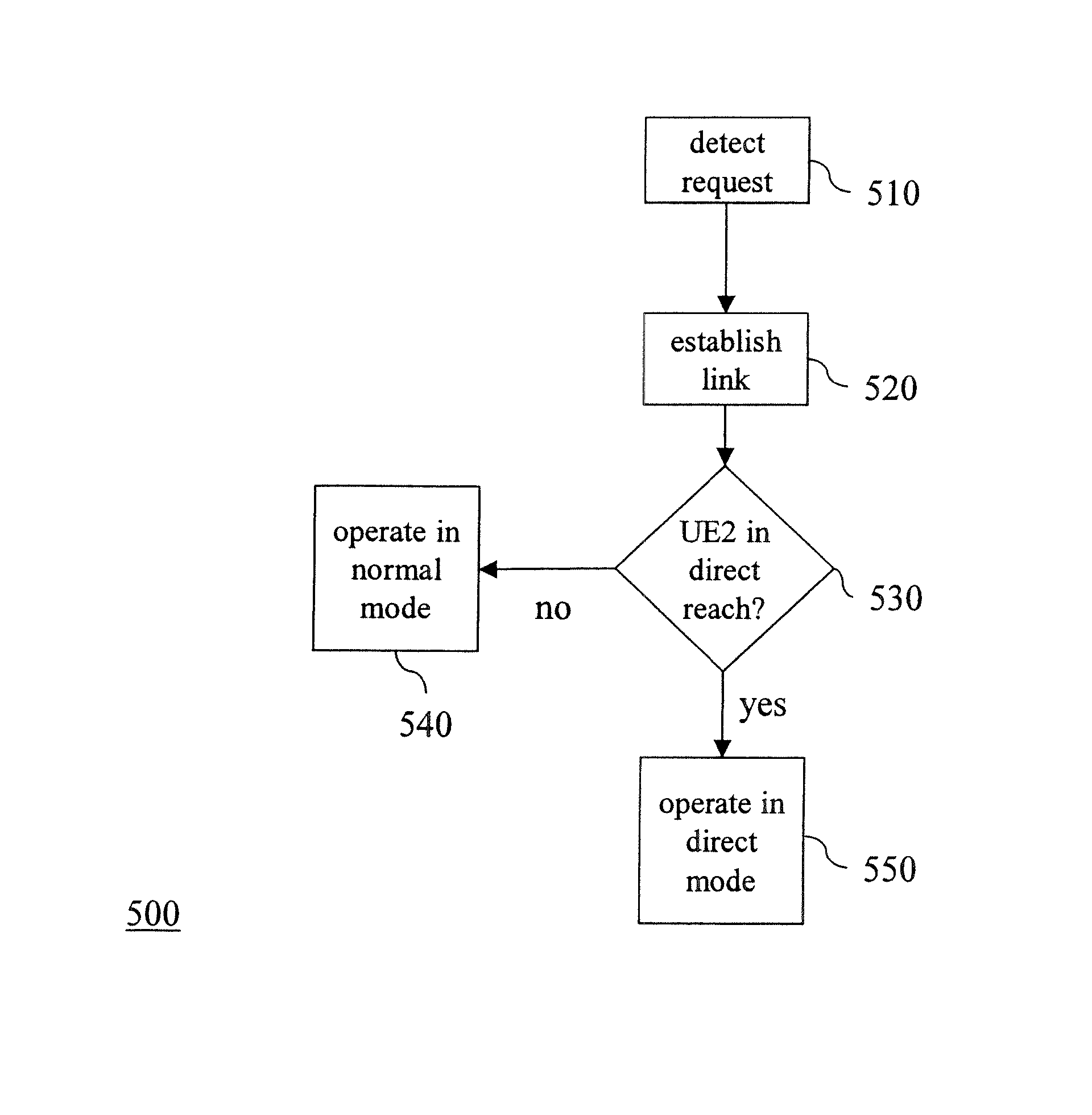
[0013] It is proposed to introduce a “direct communication” mode which allows direct communication between the user equipments controlled by one base station. There is no need to route their traffic to the core network.
[0020] When introducing the direct communication mode as defined in independent claim 1, very low latency can be achieved. Users can directly exploit full air interface capacity without any need for the operator to provide backhaul capacity for them. At the same time, existing functionalities of the base station are re-used, e.g. for scheduling and radio access control, so there is few new functions required in the base station or user equipment to support this mode. Also, it is always possible to use the normal mode of operation again and make use of the full network again, including roaming, full mobility, etc.

Problems solved by technology

One the other side, operational costs of the network are still very much determined by the transport costs inside the network, e.g. between base station and other network nodes.
Thus, data rates that could be possible with a given air interface design cannot be reached, because the bottleneck is behind the base station.
Transfer of high data rates in current mobile networks may be very costly for the operator due to high backhaul / transport costs within the network.
As another disadvantage, routing the communication via several network elements can introduce delays which are increasing the latency experienced by the user.
There is currently little means for the operator to use the existing network architecture in a more flexible way.

Method used


Image

  • Flexible network architecture with user group support
  • Flexible network architecture with user group support
  • Flexible network architecture with user group support

Examples


Embodiment Construction

[0029] The method and the network element operate in two different modes: normal mode and direct mode.

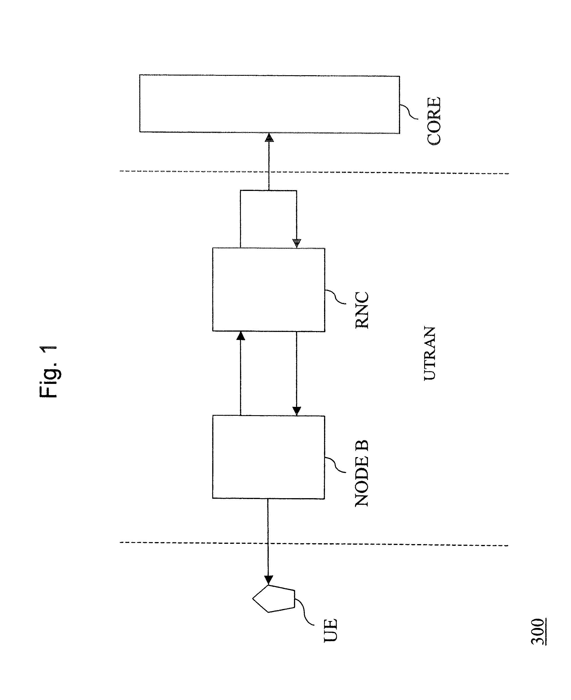
[0030]FIG. 3 is a schematic diagram showing call / connection handling in normal mode according to the state of the art. A call originating from a first User Equipment (UE1) is routed over the base station (NODE B) and the Radio Network Control (RNC) to the core network (CORE) and from there back over the same Radio Network Control (RNC) and base station (NODE B) to the second user equipment (UE2).

[0031] The base station (NODE B) is aware or may automatically find out that the second user equipment (UE2) to which the call is to be routed, is within the reach of the base station, be it in the same cell or in two logically separate cells. However, regardless of this fact, in normal mode the base station routes the call to the core network.

[0032]FIG. 4 is a schematic diagram showing in principle the operation of the network according to an embodiment of the invention, now in direct mo...


PUM


Abstract

A base station of a mobile communication network is connected to a core network and is operable in a normal mode and in a direct mode. The base station detects a request originating from a first user equipment to communicate with a second user equipment. The first user equipment is in direct reach of the base station. The base station establishes a communication link between the first and the second user equipment, and checks if the second user equipment is also within direct reach of the base station. The base station operates the communication link in direct mode, if yes, and operates the communication link in normal mode, otherwise.

Description

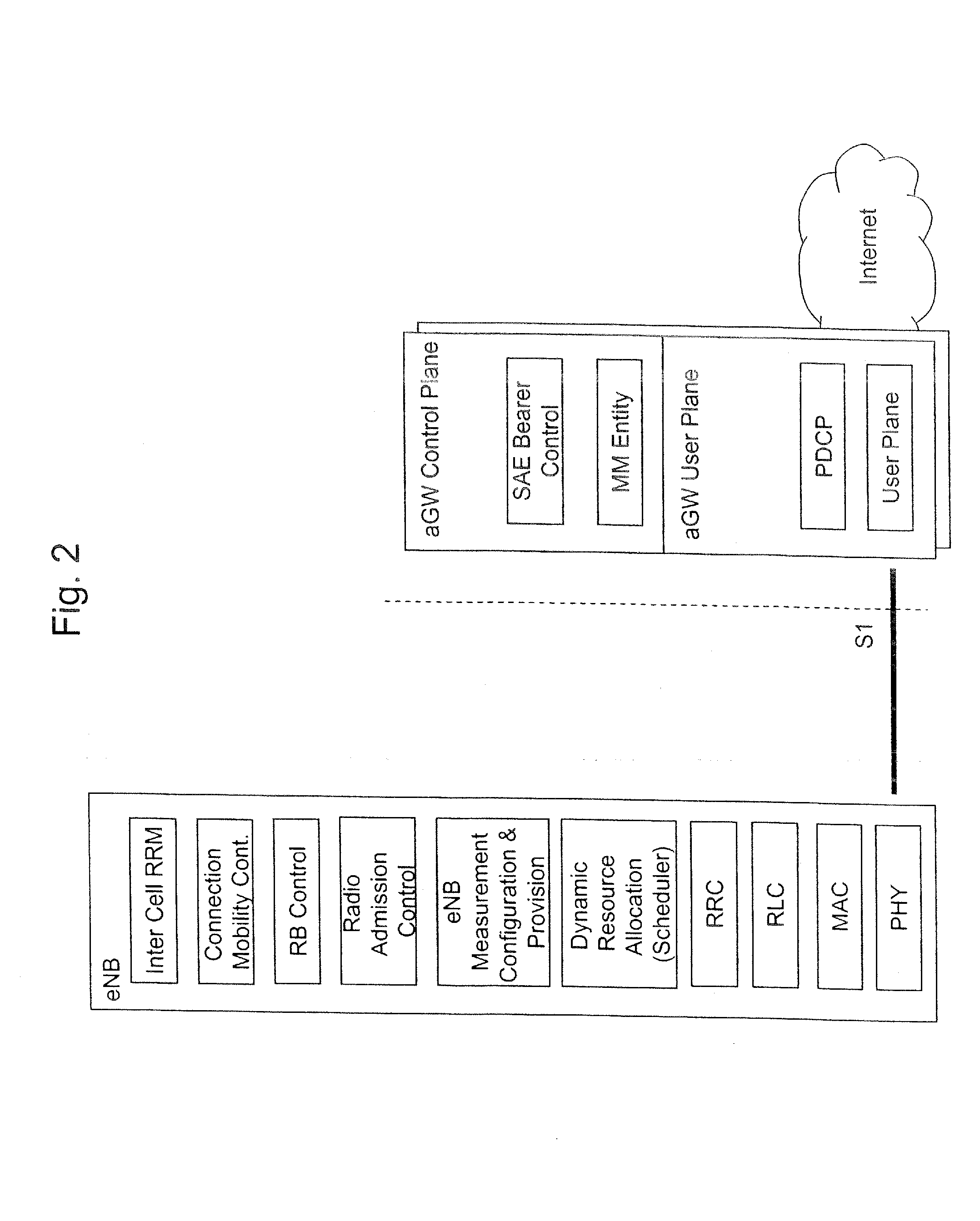
FIELD OF THE INVENTION [0001] The present invention relates to mobile communication networks. In particular, it relates to a flexible network architecture for mobile communication networks, with user group support. TECHNICAL BACKGROUND [0002] The ongoing concept work on future mobile communication systems reveals significant changes to the mobile network architecture. In order to make networks more efficient, provide higher data rates and throughput, and reduce latency in the network, new radio access technologies and network architectures are investigated, as e.g., in the context of UMTS LTE (Universal Mobile Telecommunications System Long Term Evolution). [0003] At present, a UMTS network consists of three interacting domains; Core Network (CN), UMTS Terrestrial Radio Access Network (UTRAN) and User Equipment (UE), as shown in FIG. 1. [0004] The main function of the core network is to provide switching, routing and transit for user traffic. The core network also contains the datab...

Claims


Application Information

Patent Timeline
Patent Type & Authority Applications(United States)
IPC IPC(8): H04Q7/32H04Q7/30H04W88/08
CPCH04W88/08H04W76/14H04W24/00
Inventor GESSNER, CHRISTINAPABST, ALEXANDERTIETSCHER, GERALDMOHR, KARSTEN
Owner ROHDE & SCHWARZ GMBH & CO KG
Learn More