

Measuring structure for magneto encephalographic equipment with a superconducting magnetic-shield
a superconducting magnetic shield and measuring structure technology, applied in the direction of magnetic field measurement using superconducting devices, instruments, applications, etc., can solve problems such as difficult work, and achieve the effect of small siz
Inactive Publication Date: 2008-05-08
SUMITOMO HEAVY IND LTD
View PDF13 Cites 5 Cited by
- Summary
- Abstract
- Description
- Claims
- Application Information
AI Technical Summary
Benefits of technology
The present invention provides a new way to cool a magneto encephalographic equipment in a superconducting magnetic-shield using a commercial helium refrigerator. The invention aims to solve the problem of degradation of the equipment due to noise from mechanical vibration while ensuring that the cooling capacity is not compromised. The invention provides an integrated structure that prevents heat from flowing into the cryogenic vessel and reduces the load on the helium refrigerator. The coolant used in the integrated structure is liquid helium, which is liquefied in the annular space between the inner enclosure walls of the outer enclosure, thereby reducing the amount of coolant needed. The invention also includes a vacuum-tight structure and a plurality of SQUID sensors that are cooled by the coolant in the upper closed space. The coolant consumption is compensated by the adiabatic expansion of the coolant, which allows the equipment to run without interruption. Overall, the invention provides a solution for maintaining the equipment in a stable and noise-free state while ensuring effective cooling.
Problems solved by technology
Thus, as is the case with the first enclosure of high critical temperature superconductor to prevent invasion of exterior magnetic field, the SQUID magnetic sensor can be cooled by helium gas rather than liquid helium, which is difficult to work with.
Method used
View moreImage
Smart ImageViewing Examples

Examples
first embodiment
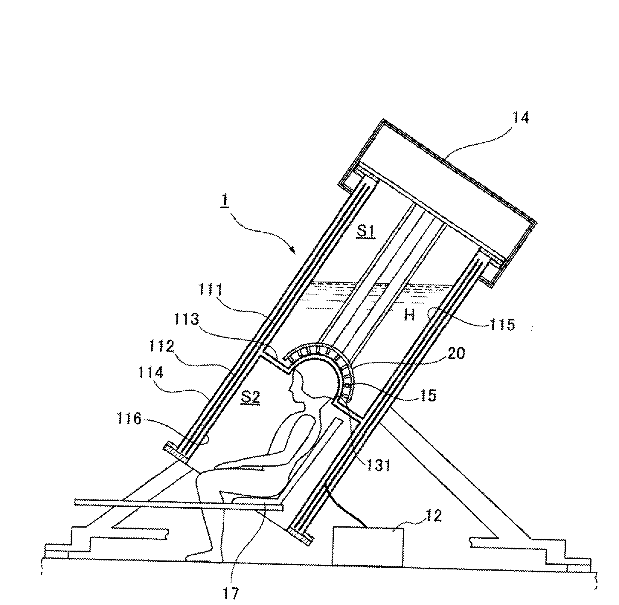
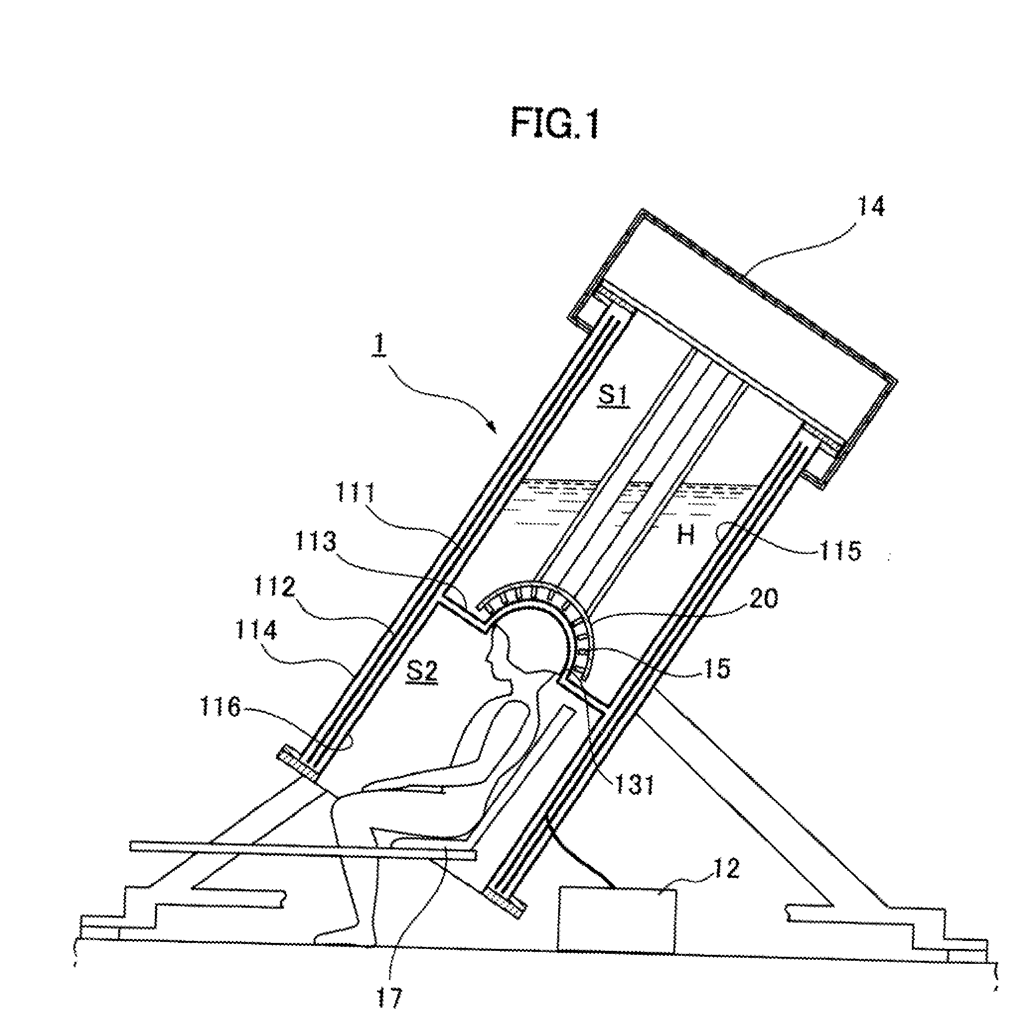
[0032]FIG. 1 illustrates a magneto encephalographic equipment using a measuring structure according to the present invention;
second embodiment
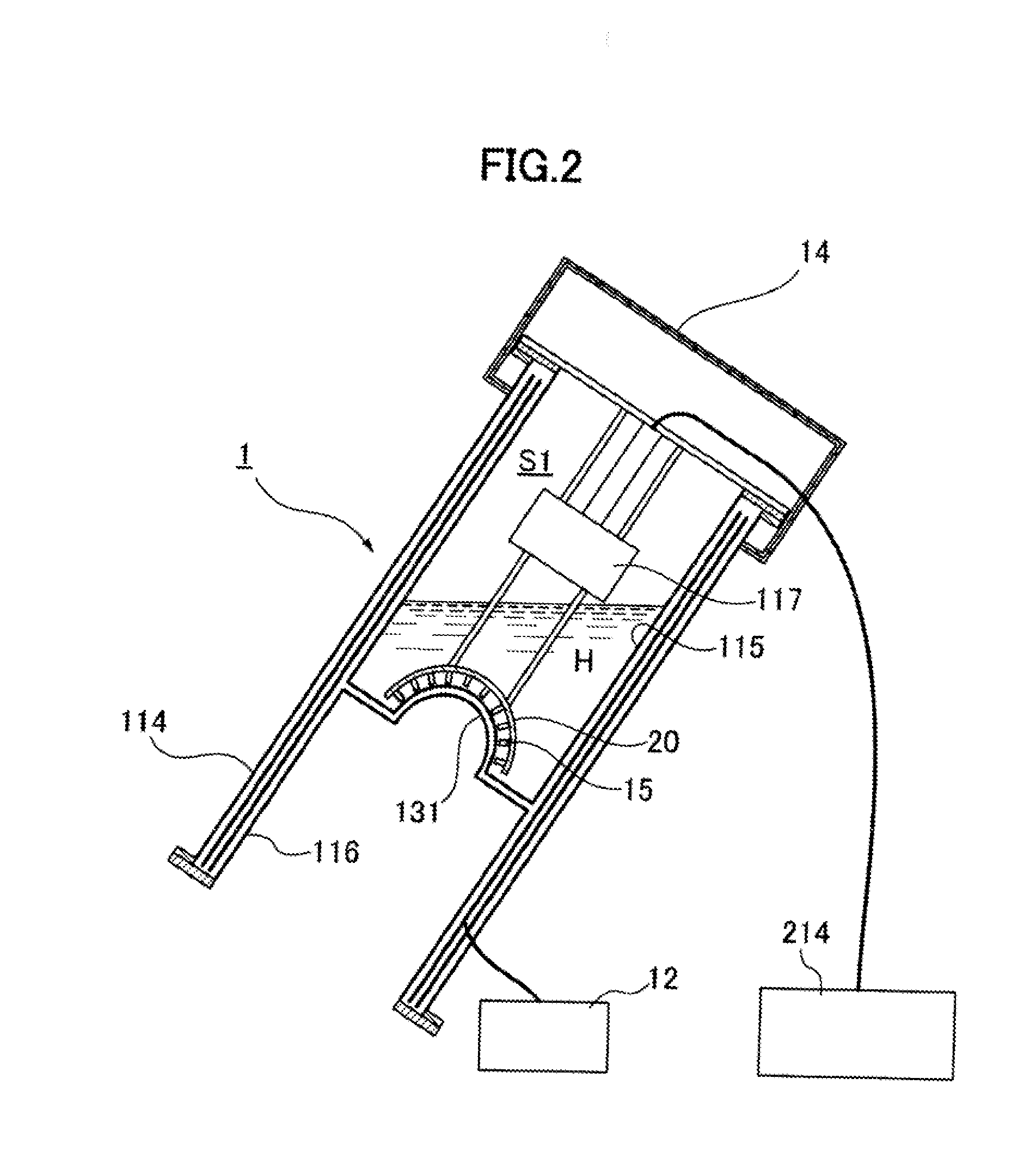
[0033]FIG. 2 illustrates a measuring structure according to the present invention;
third embodiment
[0034]FIG. 3 illustrates a measuring structure according to the present invention;
[0035]FIG. 4 illustrates a conventional magneto encephalographic equipments;
[0036]FIG. 5A illustrates the structure of the magneto encephalographic equipment according to the present invention; and
[0037]FIG. 5B illustrates the prior art structure of the magneto encephalographic equipment.
Login to View More PUM
 Abstract
Disclosed is a measuring structure for a magneto encephalographic equipment superconducting magnetic-shield comprising a vacuum-tight body comprising an outer enclosure wall, a first inner enclosure wall inserted in the outer enclosure wall to define an upper closed space, and a second inner enclosure wall to define a lower open space. The first and second inner enclosure walls are arranged with the bottom of the first inner enclosure wall facing the ceiling of the second inner enclosure wall. A first enclosure of high critical temperature superconductor and a second enclosure of high permeability material are concentrically arranged in the annular vacuum space defined between the first and second inner enclosure walls and the outer enclosure wall. A head-accommodating area is delimited by the hollow partition between the bottom of the first inner enclosure wall and the ceiling of the second inner enclosure wall both facing each other, and a plurality of SQUID sensors are arranged in the upper closed space, encircling the head-accommodating area. The SQUID sensors are cooled by the liquid helium contained in the upper closed space whereas the first enclosure is cooled by the circulating helium gas from a closed-cycle helium refrigerator. An adiabatic expansion compartment may be placed in the upper closed space. The adiabatic expansion compartment is supplied with cooled helium gas, which is converted into liquid helium by adiabatic expansion, and the so converted liquid helium is led into the liquid helium bath in the form of drops to make up for the consumption of liquid helium during operation. Otherwise, the adiabatic expansion compartment is connected to the SQUID magnetic sensors to indirectly cool the sensors by the thermal conduction body.
Description
TECHNICAL FIELD[0001]The present invention relates to a magneto encephalographic equipment for measurement of evoked neuro-magnetic field which is produced by nerve current in human brains, and is estimated to be approximately one hundred million times smaller than the magnetic field of the earth.[0002]A SQUID (Superconducting Quantum Interference Device) chip immersed in a liquid helium hath works as a magnetic sensor of high sensitivity at a very low temperature to detect such a weak magnetic field. Thus, observation of the dynamics of neural networks in human brains is enabled. So, the equipment can be used for diagnosis of function of brains (such as memory, learning, attention and other mental activities) and of some brain disorders (attention deficit, hyperactivity disorder, learning disabilities, autism or schizophrenia).BACKGROUND ART[0003]The present inventor developed an equipment for measurement of neuro-magnetic field above human heads with a SQUID cryogenically cooled b...
Claims
Login to View More Application Information
Patent Timeline
 Patent Type & AuthorityApplications(United States)
IPC IPC(8): G01R33/035
CPCG01R33/0354A61B5/04008A61B5/245Y10S505/846
InventorMATSUI, TOSHIAKIOHTA, HIROSHI
OwnerSUMITOMO HEAVY IND LTD