Locating critical dimension(s) of a layout feature in an IC design by modeling simulated intensities

Active Publication Date: 2008-05-08
SYNOPSYS INC
View PDF8 Cites 13 Cited by
  • Summary
  • Abstract
  • Description
  • Claims
  • Application Information

AI Technical Summary

Benefits of technology

[0014]A computer is programmed in accordance with the invention to perform lithography simulation at a few locations, in a transverse direction relative to a length of a feature of an IC design, to obtain simulated intensities (of performing lithography) at

Problems solved by technology

One problem with the bisection process described above is that the aerial image simulator (used to simulate the lithography process) is invoked multiple times in each iteration.
However, the just-described centerline method can result in some errors under certain circumstances, e.g. (1) if intensity peak has drifted from nominal center of the trace (due to proximity effect of adjacent traces) or (2) if a corner is present adjacent at the end of the trace.

Method used


Image

  • Locating critical dimension(s) of a layout feature in an IC design by modeling simulated intensities
  • Locating critical dimension(s) of a layout feature in an IC design by modeling simulated intensities
  • Locating critical dimension(s) of a layout feature in an IC design by modeling simulated intensities

Examples


Embodiment Construction

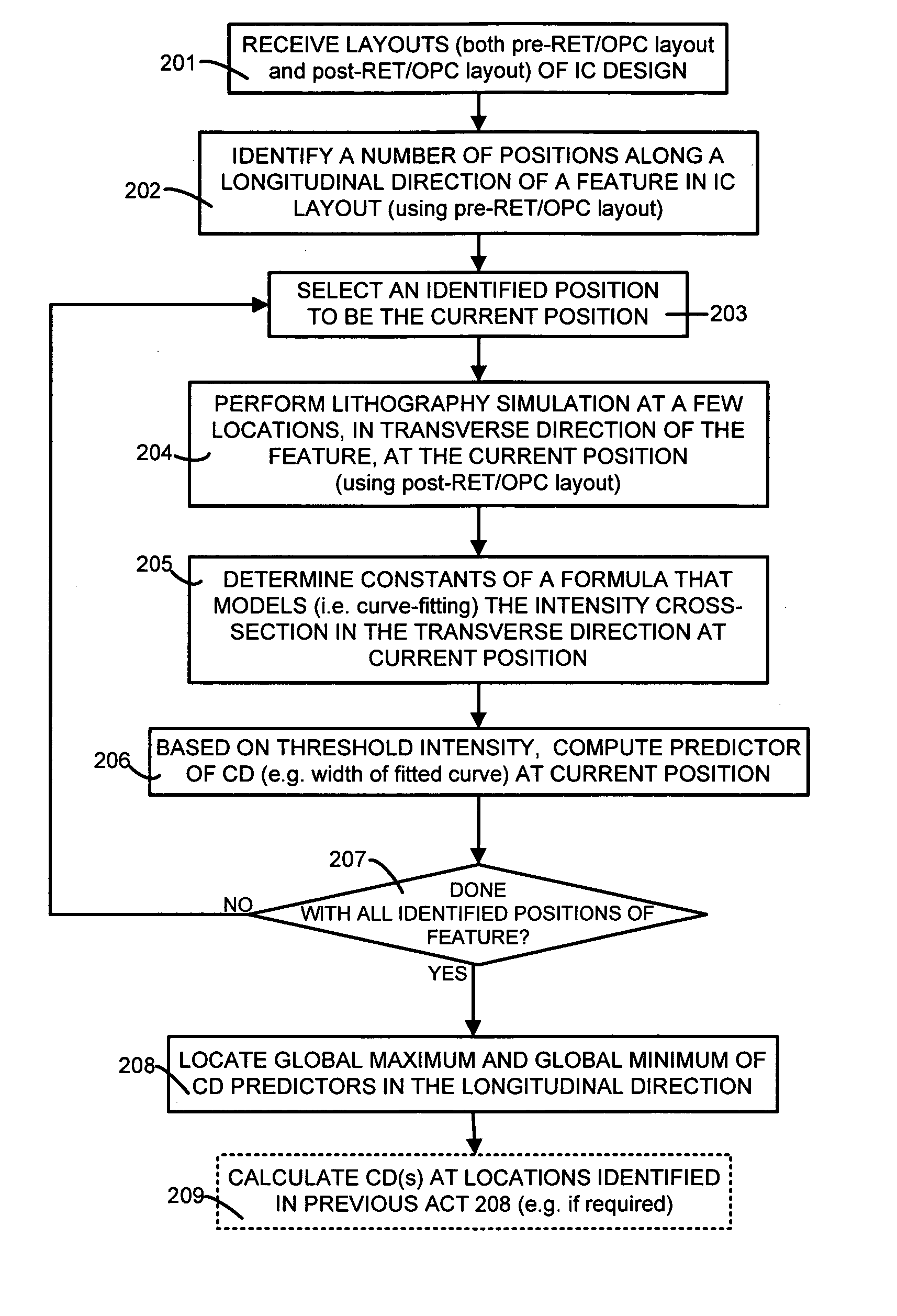
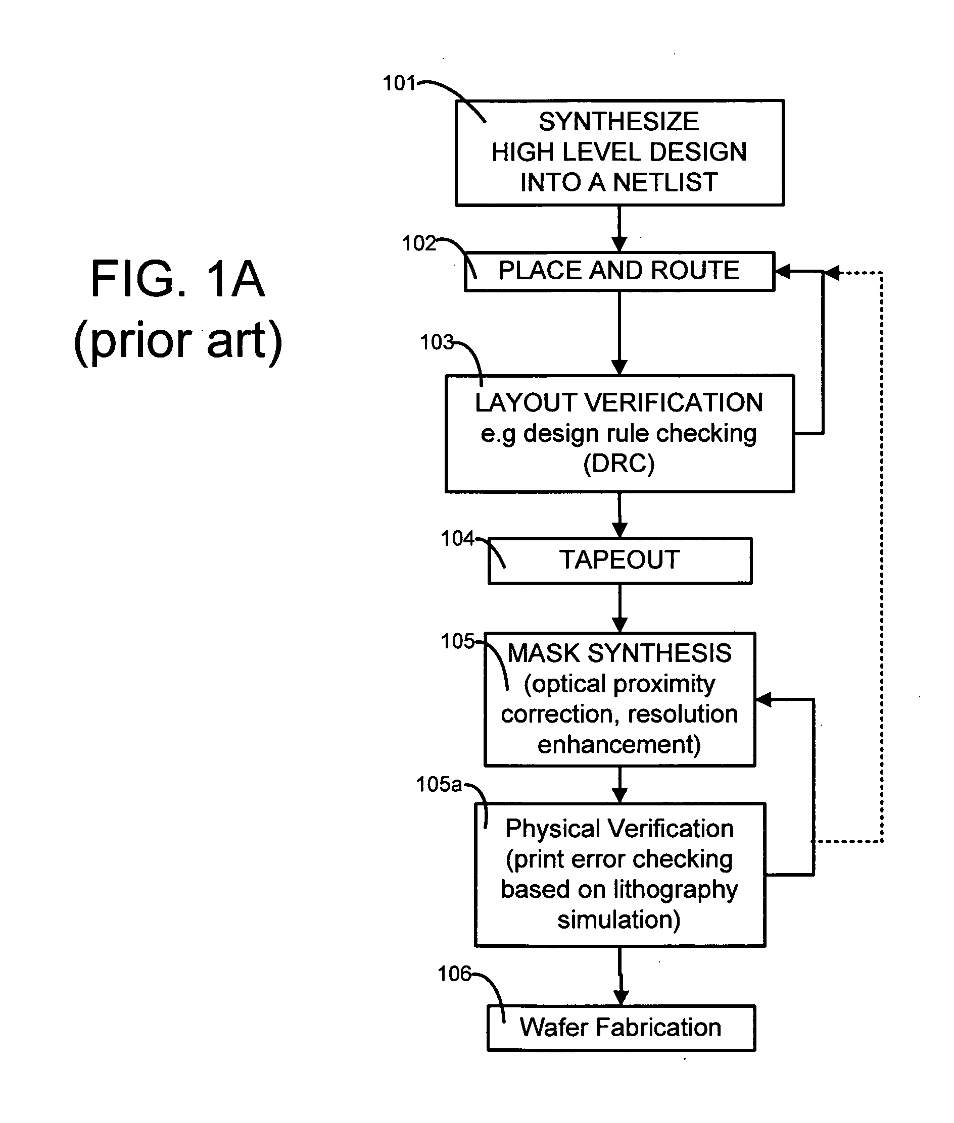
[0031]A computer 150 (FIG. 9A) is programmed, in accordance with the invention, to perform acts 201-208 (FIG. 2) after performance of a place-and-route operation 102, and a layout verification operation 103 which involves geometry-based design rule checking (DRC) to obtain a first layout (called pre-RET / OPC layout), and after performance of a mask synthesis operation 105 to obtain a second layout (called post-RET / OPC layout). Software of instructions for computer 150 to perform acts 201-208 is also referred to below as a CD locator, and is shown in FIGS. 9A and 9B as item 999. The CD locator can be used as described below, to locate a position where a critical dimension of a feature occurs. Location of the critical dimension is useful for a number of reasons, including, for example, performance of act 209 to verify acceptability of an IC layout for fabrication.

[0032]Operation 102 is performed using any prior art place-and-route tool, such as the Astro product available from Synopsys...


PUM


Abstract

A computer is programmed to perform lithography simulation at a number of locations in a transverse direction relative to a length of a feature of an IC design, to obtain simulated intensities at the locations. The computer is further programmed to determine constants of a predetermined formula that models a trend of the simulated intensities as a function of distance (in the transverse direction), by curve-fitting. The computer is also programmed to compute a value (“CD predictor”) based on the just-determined constants, the formula and a known threshold intensity for a given position along the feature's length. The just-described process, of lithography-simulation, followed by curve-fitting, followed by CD predictor computation, is repeatedly performed to obtain a number of CD predictors at a corresponding number of positions along the feature's length. The CD predictors are used to identify a position of a critical dimension, for use in, for example, layout verification.

Description

BACKGROUND[0001]1. Field of the Invention[0002]The invention relates to verification of layouts used in fabrication of semiconductor wafers that contain integrated circuits (ICs). More specifically, the invention relates to a method and an apparatus for evaluation of criteria related to critical dimension (CD), such as conformity to user specification(s) of CD and / or uniformity of linewidth.[0003]2. Related Art[0004]In the manufacture of integrated circuit (IC) chips, minimum feature sizes have been shrinking according to Moore's law. Currently the minimum feature size is smaller than the wavelength of light used in the optical imaging system. Accordingly it has become increasingly difficult to achieve reasonable fidelity (including resolution and depth of focus) between (a) a layout as designed in a prior art computer in a place and route step 101 (FIG. 1A) and (b) shapes of circuit elements formed in a wafer fabrication step 106 (FIG. 1A). Step 106 normally involves a number of pr...

Claims


Application Information

Patent Timeline
IPC IPC(8): G06F17/50
CPCG06F17/5081G06F30/398
Inventor SONG, HUAWANG, LANTIANGTANG, ZONGWU
Owner SYNOPSYS INC
Why Eureka
Try Eureka