Rotor Blade Pitch Control

a technology of rotor blades and rotor blades, which is applied in the direction of rotors, roofs, vessel construction, etc., can solve the problems of increasing the mental and physical work load of the pilot, component fatigue, and limited forward air speed of the conventional rotor aircraft, so as to improve the harmonic individual blade control, reduce vibration, and improve the speed of the rotor aircraft

Active Publication Date: 2008-05-15
THE BOEING CO
View PDF6 Cites 41 Cited by
  • Summary
  • Abstract
  • Description
  • Claims
  • Application Information

AI Technical Summary

Benefits of technology

[0010]In accordance with the exemplary embodiments thereof described herein, the present invention provides a mechanical individual blade control (MIBC) mechanism for rotor blade systems and the main rotor(s) of a rotor aircraft, such as a helicopter, that affords a simpler, more reliable, higher harmonic individual blade control technique, enables a higher rotor aircraft speed to be achieved when used in conjunction with reverse flow rotor techniques (i.e., slowed rotor speed combined with multiple blade pitch changes), results in substantially reduced vibration at either high or low speeds while avoiding the overall design complexity of the prior art IBC mechanisms, and provides a technique for effecting automatic rotor system track and balance.
[0015]In another preferred exemplary embodiment, the aircraft includes a gearbox having an opening therethrough, with the lower end of the rotor mast extending into the gearbox and the mechanical linkages extending through the opening in the gearbox such that an upper end of each of the linkages is disposed above the gearbox and a lower end of each of the linkages is disposed below the gearbox, along with the actuators. This “hole-in-the box” arrangement provides a compact, protected mechanical control system design and locates the transmission closer to the rotating plane of the blades, thereby reducing rotor stresses, since the rotating plane of the blades can be located closer to the transmission wherein the rotor mast moments are reacted, and provides the power control elements in a stationary system that is easy to inspect and maintain. The robust annular rotor mast also serves to protect the flight critical linkages of the MIBC. The hole-in-the-box design also simplifies the pitch tube anti-rotation feature, as compared to a conventional “scissor” device.
[0017]The use of the novel MIBC mechanism in combination with reverse rotor flow (slowed rotor speed, multiple blade pitch cycles per revolution), enables a more conventional rotor air-craft (i.e., a non-tilt rotor and no forward propulsion system) to 1) achieve a higher forward air-speed through use of a slowed rotor and reverse rotor flow techniques, 2) avoid the complications and weight of tilt rotor aircraft designs, 3) avoid the complication and weight of compound aircraft designs, and 4) provide higher harmonic controls to reduce vibration levels. The use of the novel MIBC in conjunction with conventional non-reverse flow rotor systems also provides: 1) a higher harmonic control (HHC) solution to reduce vibration, in that it enables the direction of pitch of each blade of the rotor to be changed more than twice, and indeed, as many times as desired, during a single revolution of the rotor hub, and 2) provides automatic rotor blade track and balance to reduce maintenance time.

Problems solved by technology

As a result of the foregoing method of operation and the effect of the relative speed of the aircraft moving through air, conventional rotor aircraft have a limited forward air speed, viz., about 180 knots (˜207 mph), due to the blade tip speed approaching the speed of sound on the advancing blade, and a stall condition occurring on the retreating blade.
Additionally, when these limiting conditions are being approached, large vibrations begin to occur in the rotor, which causes component fatigue and increased pilot mental and physical work load.
The vibrations cause the entire vehicle, including the pilot and aircraft cockpit controls, to shake and the aircraft displays to become blurred.
However, this approach adds wings, aero-surface controls, complex rotor conversion mechanisms, weight and cost.
These compound designs typically also include additional lifting surfaces and aero-surface controls, which add significant complexity, weight and cost to the aircraft.
Both approaches are complicated, add extensive installation congestion in the rotating section of the rotor system, and significantly reduce control reliability of the “flight critical” rotor system.
The electric approach utilizes a screw mechanism that is susceptible to jamming and is dependent on slip ring technology, which is unreliable.
Furthermore, lightening strike attachment to the rotor hub is a common occurrence and may completely eliminate all electrical control.
The hydraulic approach is dependant on both electrical and hydraulic slip ring technology, neither of which is reliable.
The lightening strike problem also exists with this design.
External hydraulic leaks are centrifugally distributed onto numerous aircraft components, including the exterior body and windshield and require extensive clean up.
In light of the foregoing problems, there is a long felt but as yet unsatisfied need in the field of rotor aircraft for a simpler, substantially more reliable, less expensive and lighter weight mechanism for providing individual blade control (IBC) for the rotor(s) of a rotor aircraft.

Method used


Image

  • Rotor Blade Pitch Control
  • Rotor Blade Pitch Control
  • Rotor Blade Pitch Control

Examples


Embodiment Construction

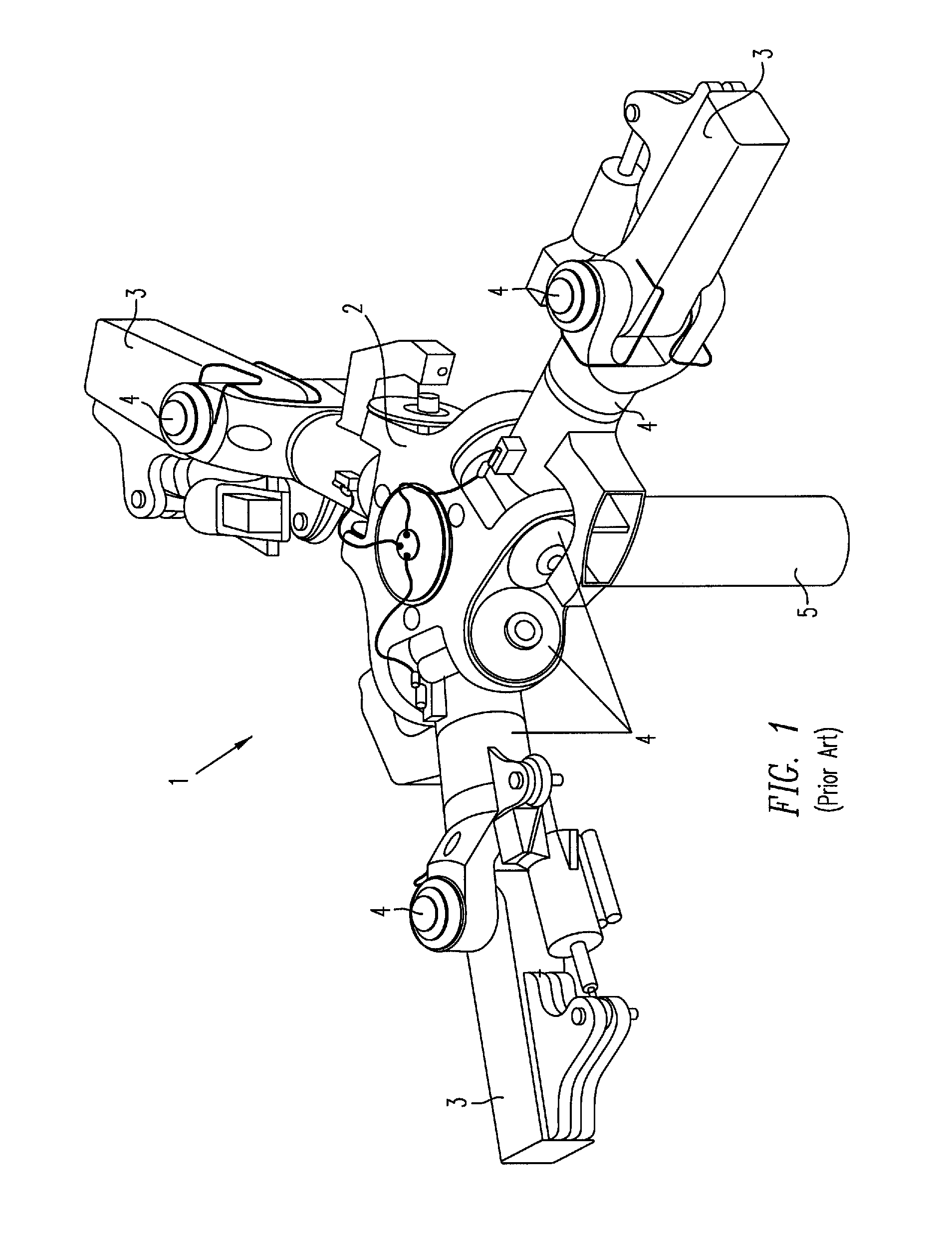
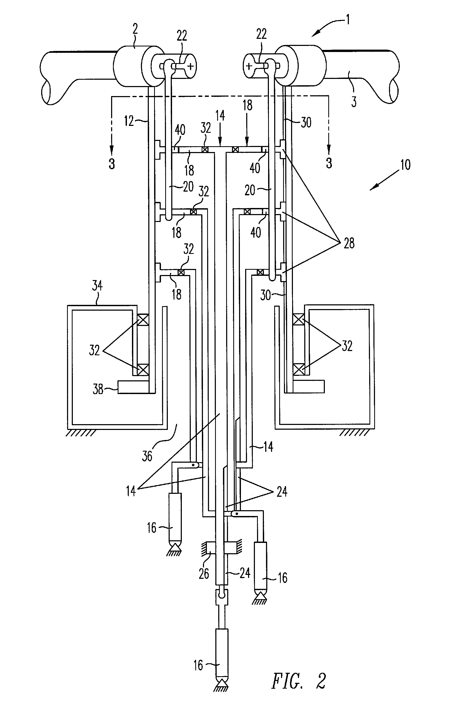
[0022]FIG. 2 is a partial cross-sectional view of a main rotor 1 of a rotor aircraft (not illustrated) incorporating an exemplary embodiment of a mechanical independent blade control (MIBC) mechanism 10 in accordance with the present invention, and FIG. 3 is a cross-sectional view of the MIBC mechanism 10 of FIG. 2, as seen along the section lines 3-3 taken in FIG. 2.

[0023]In accordance with the present invention, the MIBC 10 provides reliable higher harmonic individual blade control (IBC). The higher harmonic IBC solution, in turn, enables 1) a higher rotor aircraft speed when used in conjunction with reverse flow rotor techniques (i.e., slowed rotor speed, multiple blade pitch cycles per revolution) in a more conventional rotor aircraft design, 2) reduced vibration at high or low speeds in such aircraft designs while minimizing overall air-craft design complexity, thereby avoiding the complexity of tilt rotor aircraft designs and other compound aircraft designs that have addition ...


PUM


Abstract

A mechanical independent blade control (MIBC) mechanism for controlling the pitch of each of the blades of a rotor blade system or a main rotor of a rotor aircraft independently of the other blades includes a plurality of actuators disposed in the fuselage below the hub of the rotor, each being operable to selectively control the pitch of an associated one of the blades independently of the other blades, and a plurality of mechanical linkages disposed within the annulus of the rotor mast, each coupled between a blade and an actuator and operable to transmit a force output by the actuator to a pitch horn fixed to an inner end of the associated blade. The mechanism enables the direction of pitch of each blade to be changed more than twice during one revolution of the rotor.

Description

BACKGROUND[0001]This invention relates to rotor blade systems and rotor aircraft, such as helicopters, in general, and in particular, to a mechanism that enables the pitch of each of the blades of the main rotor of the aircraft to be controlled individually and independently of the others.[0002]As illustrated in the partial perspective view of FIG. 1, most rotor aircraft, such as helicopters, include one or more power driven main rotors 1 that are equipped with a hub 2 rotatably supported on a rotor mast 5 and having a plurality of elongated blades 3 extending radially outward from it, each of which has an airfoil cross-section (not illustrated) and is coupled to the hub at the inner end thereof by three hinges 4 that enable the blade to rotate about three axes relative to the hub, i.e., to “flap” up and down, to “lag” forward and aft, and to “pitch” up and down and thereby change its angle of attack relative to the stream of air moving past it.[0003]To move the aircraft vertically,...

Claims


Application Information

Patent Timeline
Patent Type & Authority Applications(United States)
IPC IPC(8): B62D25/06
CPCB64C27/605
Inventor ZIERTEN, DANIEL T.
Owner THE BOEING CO
Why Eureka
Try Eureka