
Systems and Arrangements for Controlling Phase Locked Loop

a phase lock loop and phase lock technology, applied in the direction of pulse automatic control, electrical equipment, etc., can solve the problems of significant technological challenge to synchronization, serious degradation of system performance, and many design challenges, and achieve the effect of low jitter, high speed and easy establishmen

Inactive Publication Date: 2008-05-15
IBM CORP
View PDF22 Cites 39 Cited by
  • Summary
  • Abstract
  • Description
  • Claims
  • Application Information

AI Technical Summary

Benefits of technology

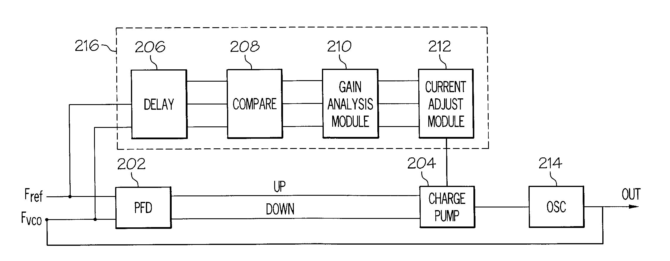
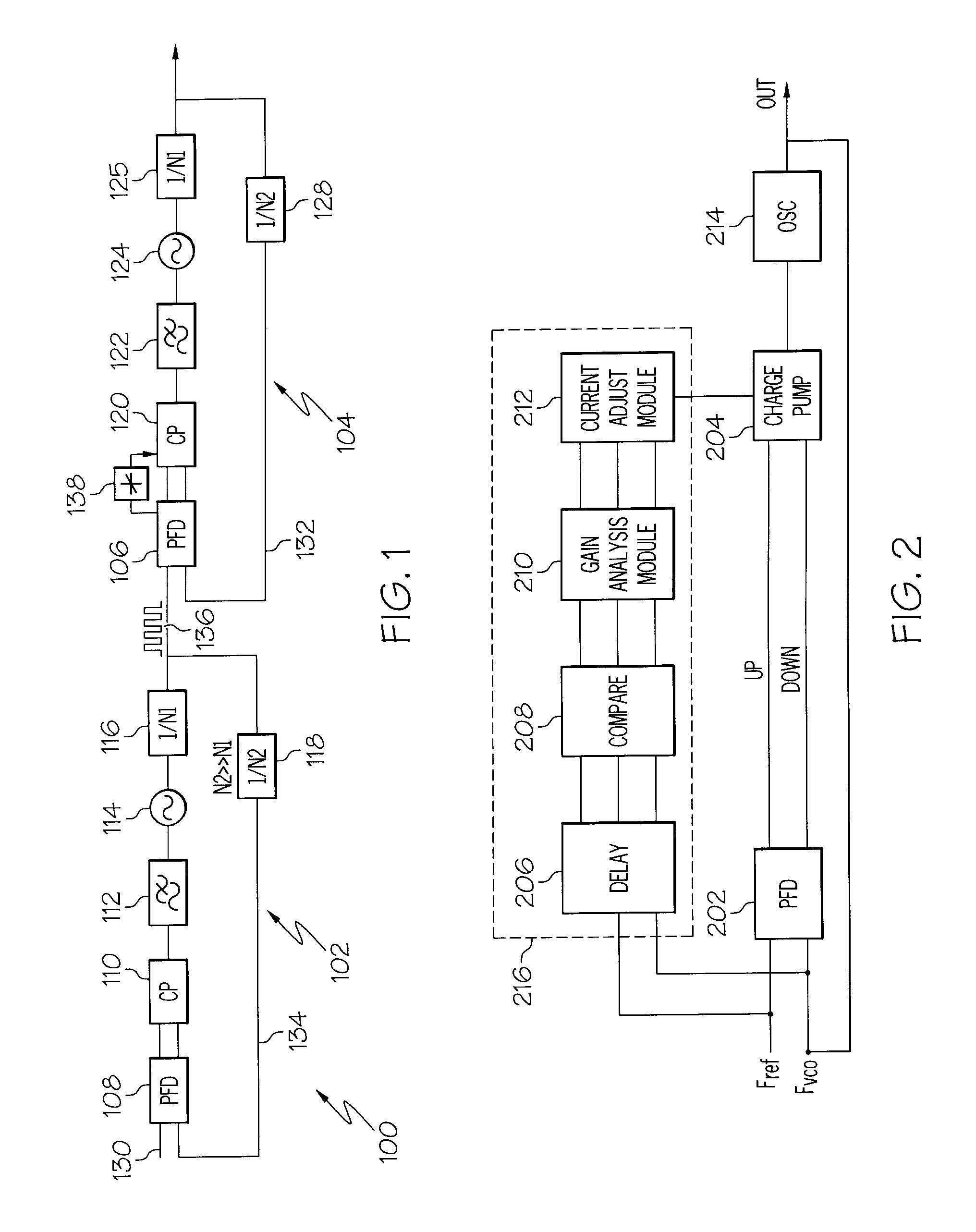
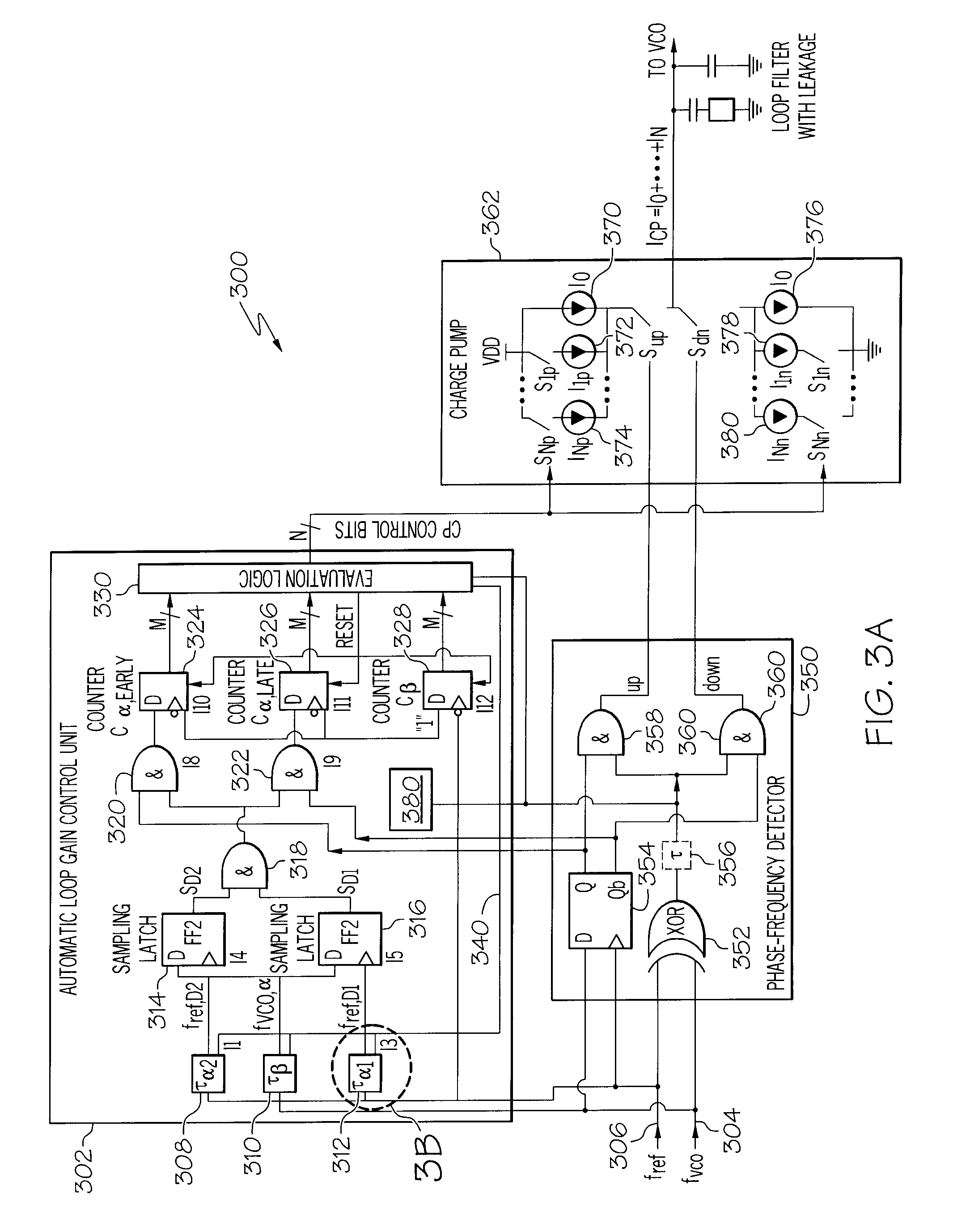
[0009]The problems identified above are in large part addressed by the systems, methods and media disclosed herein to provide a high speed, low jitter phase locked loop (PLL) with adjustable loop gain features. Thus, a multi-Gigahertz PLL, having self-adjusting gain features responsive to monitored operational phenomena or PLL properties is disclosed. In one embodiment, properties of a fVCO signal of a PLL can be acquired. These properties can include the number of occurrences or frequency and magnitude of different types of jitter on fVCO and, on the lock status of the loop. A gain control module can provide variable gain control of at least a portion of the PLL loop based on an analysis of the acquired properties. For example, when the loop is locked or when loop filter leakage is detected, the loop gain characteristics of the PLL can be adjusted via the charge pump where it has been determined that control of the loop gain is easier to establish than with other loop components such as the oscillator, or the phase frequency detector. Such a location reduces the number of controller circuits. When the acquired properties indicate that a charge pump mismatch is occurring or has occurred, control signals can be provided to the charge pump to correct the mismatch.

Problems solved by technology

As clock speeds and data rates increase into the multi Gigahertz / Gigabit per second range, many design challenges arise.
For example, jitter becomes a significant factor in clock signals because it can cause serious degradation in system performance.
It is a significant technological challenge to synchronize the timing of the receiver with the incoming data waveform at such high frequencies.
At higher clock frequencies, PLLs are commonly a source of jitter.
As mentioned above, PLL jitter becomes a significant problem at higher clock frequencies such as clock frequencies in the Gigahertz range.
However, such a high frequency feedback loop signal typically prohibits using a conventional sequential phase frequency detector (PFD) with an internal feedback loop in the PLL circuit.
The PFD is typically the input stage of a PLL and traditional PFDs cannot switch fast enough to accommodate this high frequency input.
When operating in the multi-Gigahertz range PLL designs can have many problems including control problems in a “dead zone” when the PLL is close to “phase-lock.” The PLL can be so close to phase lock that the feedback frequency does not have the gain resolution required to achieve a lock and the output frequency will overshoot and undershoot the desired frequency during the locking process for a number of cycles.
One problem with the above mentioned feed forward PFDs is that the gain of such a PFD can be relatively high, or higher than traditional PFDs.
For example, noise on the input of the PFD can be amplified by a PFD with a higher gain leading to such PLL instability.
Accordingly, specific levels of gain are desirable for specific stages or modes of operation and specific components of a PLL during the specific modes of operation and other levels of gain are undesirable for specific stages of the PLL during other modes of PLL operation.

Method used


Image

  • Systems and Arrangements for Controlling Phase Locked Loop
  • Systems and Arrangements for Controlling Phase Locked Loop
  • Systems and Arrangements for Controlling Phase Locked Loop

Examples


Embodiment Construction

[0026]The following is a detailed description of embodiments of the disclosure depicted in the accompanying drawings. The embodiments are in such detail as to clearly communicate the disclosure. However, the amount of detail offered is not intended to limit the anticipated variations of embodiments; on the contrary, the intention is to cover all modifications, equivalents, and alternatives falling within the spirit and scope of the present disclosure as defined by the appended claims. The descriptions below are designed to make such embodiments obvious to a person of ordinary skill in the art.

[0027]While specific embodiments will be described below with reference to particular configurations of hardware and / or software, those of skill in the art will realize that embodiments of the present invention may advantageously be implemented with other equivalent hardware and / or software systems. Aspects of the disclosure described herein may be stored or distributed on computer-readable med...


PUM


Abstract

A multi-Gigahertz, low jitter phase locked loop (PLL) with adjustable gain is disclosed. In one embodiment, properties of a fVCO signal of a PLL can be acquired. Properties can include the occurrences of different types of jitter on the fVCO signal and the lock status of the PLL. A gain control module can control at least a portion of the PLL based on an analysis of the acquired properties. For example, when the loop is locked or when there is loop filter leakage, the gain of a charge pump in the PLL can be reduced. When a charge pump mismatch is detected based on the acquired properties, additional control signals can be provided to the charge pump to correct the mismatch.

Description

FIELD OF INVENTION[0001]The present disclosure pertains to the field of clock generating circuits and further to the field of phase locked loops.BACKGROUND[0002]Generally, each new generation of electronic equipment processes data at higher speeds and can communicate at higher speeds. Accordingly, clocks that run such electronic devices are required to operate at higher speeds in each new generation of devices. As clock speeds and data rates increase into the multi Gigahertz / Gigabit per second range, many design challenges arise. For example, jitter becomes a significant factor in clock signals because it can cause serious degradation in system performance. Jitter can be defined as a “shaky” pulse or a deviation, variation, or displacement of some portion of a clock pulse from a desired shape. This deviation often includes amplitude variations, phase timing width variations and / or just a pulse or a period frequency that becomes displaced from the desired shape.[0003]Generally, clock...

Claims


Application Information

Patent Timeline
IPC IPC(8): H03L7/089
CPCH03L7/0898H03L7/095H03L7/23H03L7/1072H03L7/107H03L7/089
Inventor CRANFORD, HAYDEN C.KOSSEL, MARCEL A.TOIFL, THOMAS H.
Owner IBM CORP
Learn More