
Differential m phase-shift modulator

a technology of phase shift modulator and phase shift module, which is applied in the direction of digital transmission, electromagnetic transceivers, instruments, etc., can solve the problems of complex module configuration and chip configuration of the modulator, and achieve the effect of advantageously reducing power consumption and increasing the length of the electrod

Inactive Publication Date: 2008-05-15
FUJITSU LTD
View PDF8 Cites 30 Cited by
  • Summary
  • Abstract
  • Description
  • Claims
  • Application Information

AI Technical Summary

Benefits of technology

[0015]Another object of the present invention is to achieve lower power consumption of the M phase-shift modulator.
[0032]According to the present invention, as described above, a phase-shift voltage to produce a phase shift difference of substantially 2π / 4 (M) for the n signal lights multiplexed by the multiplexing waveguide can be applied to the two (n) Mach-Zehnder type light modulators together with the driving voltage signal, and therefore a function corresponding to a π / 2 phase shifter in a conventional technique can be added to the two (n) Mach-Zehnder type light modulators and a waveguide space reserved for mounting the π / 2 phase shifter can be left out, achieving reduction in device size. In addition, by selecting the waveguide space reserved for mounting the π / 2 phase shifter as a formation area of the two (n) Mach-Zehnder type light modulators, electrode lengths can be increased while maintaining the existing device size, and therefore power consumption can advantageously be reduced by towering the voltage applied to the electrodes.

Problems solved by technology

There is also a problem that, in addition to components such as the child MZ type light modulators 101 and 102, the π / 2 phase shifter 104 is needed, and therefore the chip configuration and module configuration of the modulator become complicated.

Method used


Image

  • Differential m phase-shift modulator
  • Differential m phase-shift modulator
  • Differential m phase-shift modulator

Examples


first embodiment

[A] Description of the First Embodiment

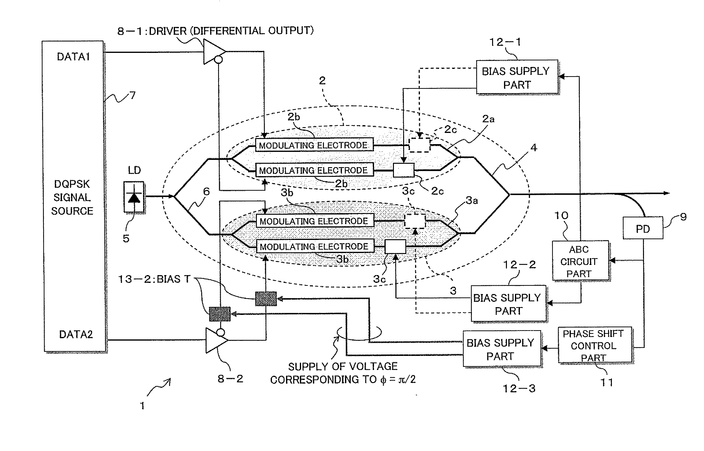
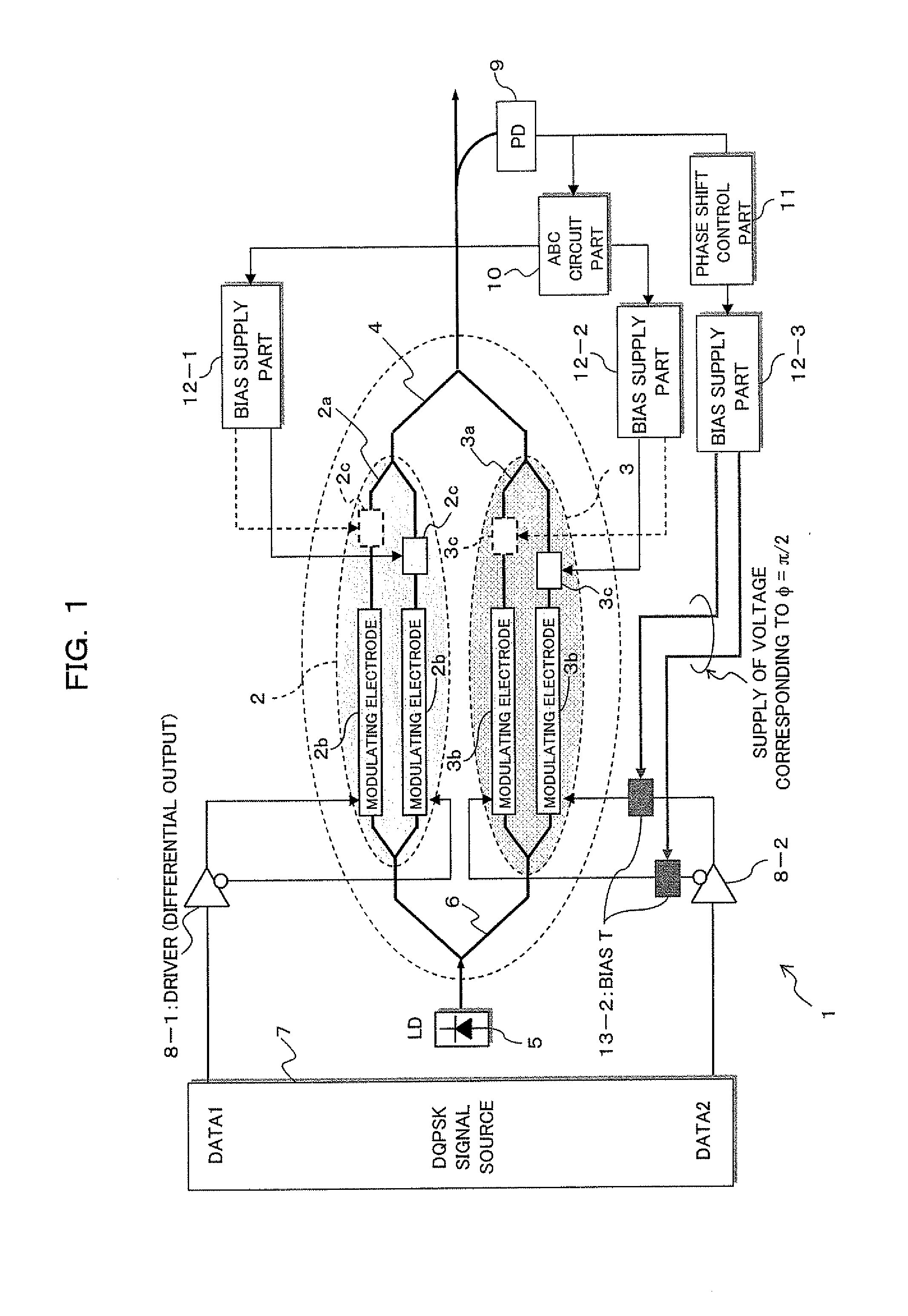
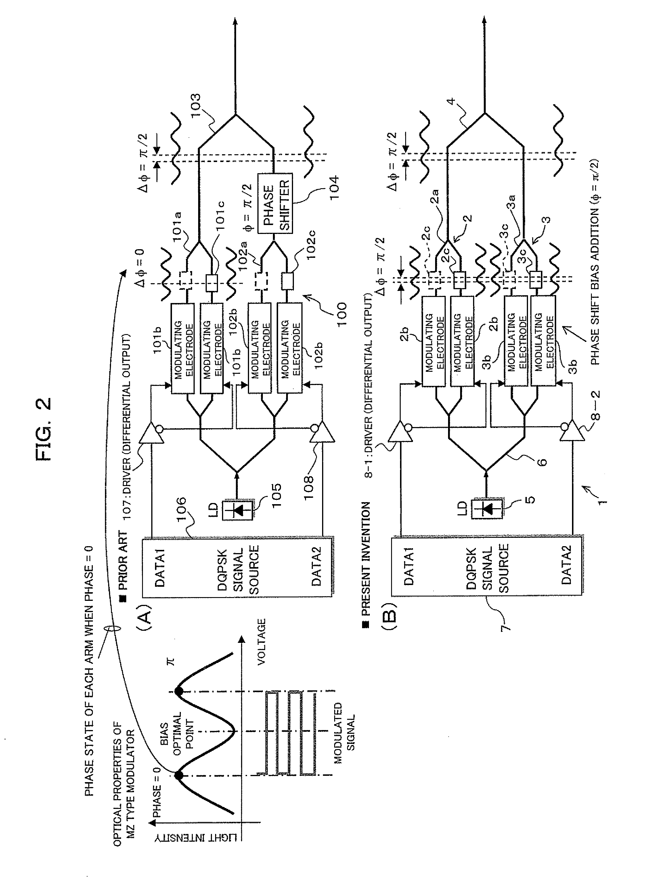
[0043]FIG. 1 is a diagram showing a DQPSK modulator 1 according to the first embodiment of the present invention. The DQPSK modulator 1 shown in FIG. 1 comprises a first MZ type light modulator 2, a second MZ type light modulator 3, and a multiplexing waveguide 4, and together with these components, the DQPSK modulator 1 can also be constructed by including a light source 5 composed of LD, a demultiplexing waveguide 6, a DQPSK signal source 7, drivers 8-1 and 8-2, a photo diode (PD) 9, an ABC (Automatic Bias Control) circuit part 10, a phase shift control part 11, bias supply parts 12-1 to 12-3, and a bias-T 13-2.

[0044]Here, the DQPSK signal source 7 generates original data (DATA1 and DATA2) for modulation as a DQPSK signal light, and the drivers 8-1 and 8-2 amplify electric signals based on (pre-code processed) first data and second data (DATA1, DATA2) from the DQPSK signal source 7 to supply the electric signals to the first MZ type light mod...

second embodiment

[B] Description of the Second Embodiment

[0085]FIG. 8 is a diagram showing a DQPSK modulator 21 according to a second embodiment of the present invention. The DQPSK modulator 21 shown in FIG. 8 is different from the DQPSK modulator 1 in the aforementioned first embodiment in a supply mode of the bias voltage to each of first and second MZ type light modulators 22 and 23 along with the configuration of each of the first and second MZ type light modulators 22 and 23 (See numerals 1 and 2 in FIG. 1). Otherwise, the configuration is basically the same as that of the DQPSK modulator 1 shown in FIG. 1 and the same numerals in FIG. 8 as those in FIG. 1 denote approximately the same components.

[0086]Here, the first and second MZ type light modulators 22 and 23 have the first and second MZ type optical waveguides 2a and 3a like the aforementioned first embodiment and also electrodes 2d and 3d for modulation / bias shared use respectively.

[0087]The electrode 2d is formed on both arms constitutin...


PUM

PropertyMeasurementUnit
phase shiftaaaaaaaaaa
phase-aaaaaaaaaa
voltageaaaaaaaaaa

Abstract

The present invention is a miniaturized differential M phase-shift modulator (M=2n: n is 2 or more) in which a plurality of Mach-Zehnder type light modulators each adapted to output a DPSK-modulated signal light by applying a driving voltage signal are arranged in parallel and that comprises a multiplexing waveguide adapted to output a DMPSK-modulated light by multiplexing outputs of the plurality of the Mach-Zehnder type light modulators, wherein a phase-shift voltage to produce a phase shift difference of substantially 2π / M for a plurality of the signal lights multiplexed by the multiplexing waveguide is applied to the plurality of the Mach-Zehnder type light modulators together with the driving voltage signal.

Description

BACKGROUND OF THE INVENTION[0001]1) Field of the Invention[0002]The present invention relates to a differential M phase-shift modulator (M: M=2n), and particularly to a differential M phase-shift modulator suitable in use for a transmitter in an optical transmission system.[0003]2) Description of the Related Art[0004]In recent years, demand has increasingly been growing for installation of a next-generation 40-Gbit / s optical transmission system, and also a transmission distance and frequency utilization efficiency similar to those of a 10-Gbit / s optical transmission system have been demanded. As an implementation means thereof, research and development of the DPSK (Differential Phase Shift Keying) modulation method, which is superior to the NRZ (Non return to Zero) modulation method conventionally applied to systems of 10 Gbit / s or below in optical signal to noise ratio (OSNR) strength and nonlinear strength, has been boosted. Further, in addition to the aforementioned modulation me...

Claims


Application Information

Patent Timeline
Patent Type & Authority Applications(United States)
IPC IPC(8): H04B10/12H04B10/04G02F1/01H04B10/07H04B10/40H04B10/50H04B10/516H04B10/54H04B10/548H04B10/564H04B10/588H04B10/60H04B10/61H10N39/00
CPCG02F1/0123G02F1/2255G02F2001/212H04L27/2096H04B10/5561H04L27/205G02F2203/20G02F1/212
Inventor TANAKA, TOSHIKIMIYATA, HIDEYUKI
Owner FUJITSU LTD
Features
  • Generate Ideas
  • Intellectual Property
  • Life Sciences
  • Materials
  • Tech Scout
  • Unparalleled Data Quality
  • Higher Quality Content
  • 60% Fewer Hallucinations
Learn More