Process for manufacturing composite sintered machine components

a technology of composite sintered machine components and manufacturing process, which is applied in the direction of manufacturing tools, gearing details, mechanical apparatuses, etc., can solve the problems of difficult to obtain the required strength level, difficult to unitarily form the parts in a die, etc. , to achieve the effect of inappropriate composing of raw powders and insufficient bonding strength

Inactive Publication Date: 2008-05-15
HITACHI POWDERED METALS COMPANY
View PDF5 Cites 2 Cited by
  • Summary
  • Abstract
  • Description
  • Claims
  • Application Information

AI Technical Summary

Benefits of technology

[0015]An object of the present invention is to provide a process for manufacturing composite sintered machine components such as planetary carriers. In the composite sintered machine components, when a compact of an outer member having plural pillars and a compact of an inner member having hole portions corresponding to the pillars of the compact of the outer member are tightly fitted and sintered so as to bond each other, the outer member and the inner member can be bonded with a sufficient bonding strength without utilizing a difference in thermal expansion thereof in a high temperature range during sintering, and deflections of the outer member and the inner member, and deformations and fractures of thin portion of the outer member can be avoided.
[0019]According to the present invention, the circumferential side surface of the pillars of the inner member and the circumferential side surface of the hole of the outer member are interference fitted at 0 to 0.03 mm of the interference, and a sufficient bonding strength is thereby obtained. The radial side surface of the pillars and the radial side surface of the hole are interference fitted at not more than 0.01 mm of the interference or are through fitted (interference is minus), whereby a deformation and a fracture of thin portion of the outer member can be avoided. Moreover, the inner member and the outer member can be made from raw powders having the same composition, whereby a step for preparing different raw powders for the inner member and the outer member can be omitted, and an error such as an inappropriate composing of raw powders can be avoided.

Problems solved by technology

Thus, since a planetary carrier has such a complicated structure, if it is mass-produced by machining process such as cutting, great number of processing steps are required, whereby there are disadvantages in cost and accuracy of shape and size.
Therefore, planetary carriers are usually manufactured by a powdered metallurgical method that is suitable for manufacturing products uniformly in large quantities; however, in the case of planetary carriers having openings forming undercuts, which are provided on a drum, it is difficult to form them unitarily in a die.
Moreover, the bonding strength of the disk-shaped member 30 and the body member 40 mainly depends on the strength of the brazing metal, whereby it is difficult to obtain the required level of strength.
According to the methods, the above-mentioned misalignments of the centers and the phases do not occur, but the bonding surfaces of the inner member and the outer member tend to be insufficiently bonded each other, and the required level of the bonding strength may not be obtained.
Since the planetary carrier is formed by arranging flanges at both ends of the pillars, if the degree of parallelization is lost in this way, the shape is difficult to correct by applying pressure again.
Therefore, deflection that occurred during sintering and bonding will be a disadvantage in manufacturing.

Method used


Image

  • Process for manufacturing composite sintered machine components
  • Process for manufacturing composite sintered machine components
  • Process for manufacturing composite sintered machine components

Examples


embodiments

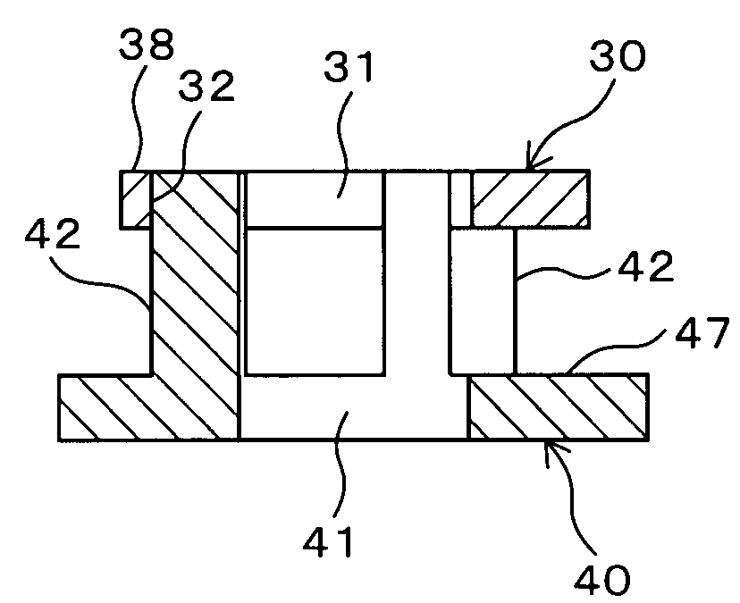
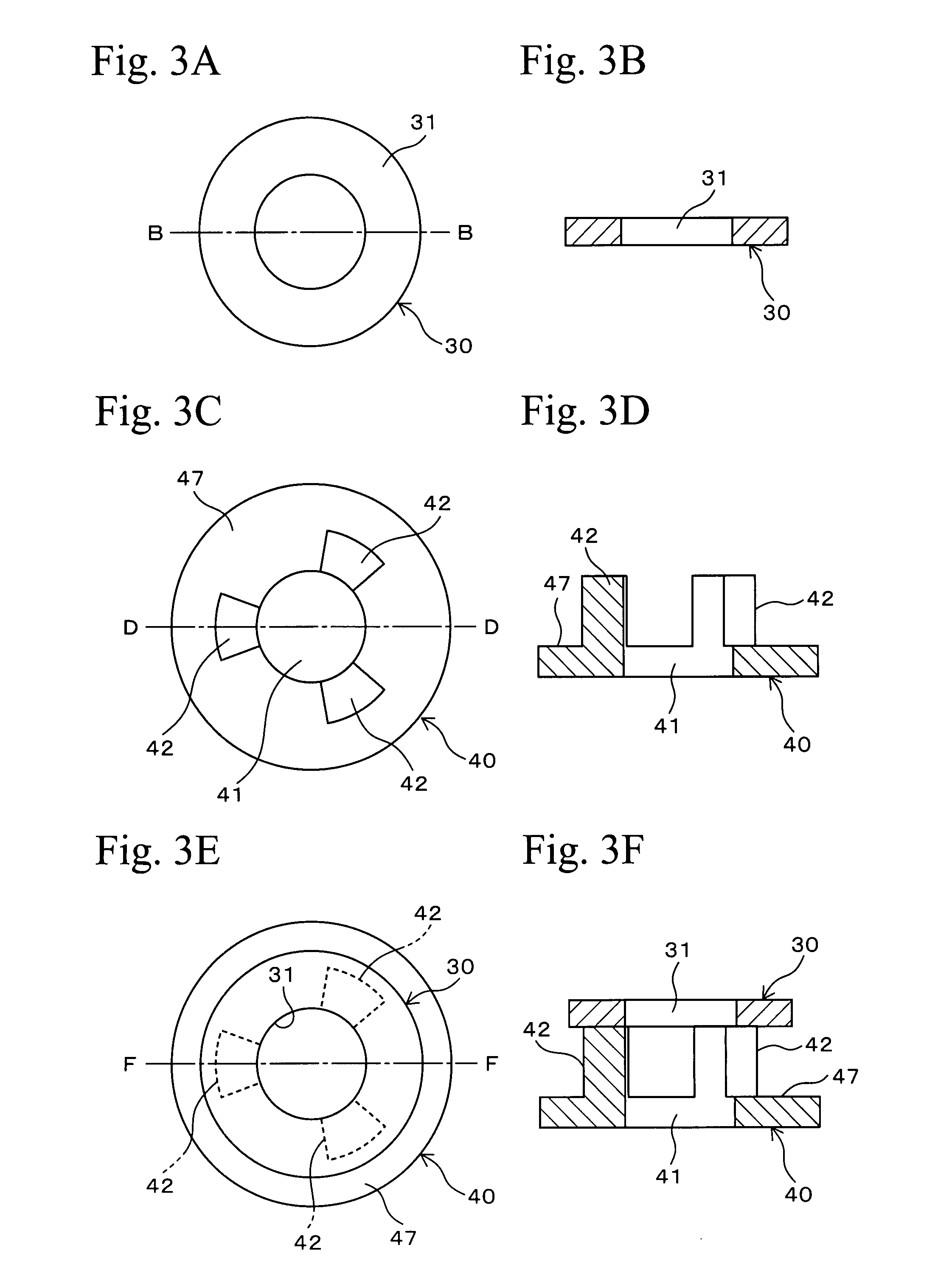
[0036]Compacts of a body member having the same structure as the body member 40 and a compact of a disk-shaped member having the same structure as the disk-shaped member 30 as shown in FIGS. 4A to 4F were formed by the following processes. In the body member 40, a disk portion 47 was 40 mm in outer diameter, a center shaft hole 41 was 11 mm in diameter, the thickness was 6 mm, and pillars 42 were radially arranged at equal intervals in a standing manner at the periphery of the center shaft hole 41. In the pillar 42, the height was 18 mm, an outer peripheral surface, that is, a radial side surface 44 was 14 mm in radius, an inner peripheral surface was 5.5 mm in radius, and both circumferential side surfaces 45 were fan-shaped in cross section with an open angle of 36°. In the disk-shaped member 30, an outer diameter was 34 mm, a center shaft hole 31 was 11 mm in diameter, the thickness was 6 mm, and three holes 32 that were connected to the center shaft hole 31 and corresponded to t...


PUM

PropertyMeasurementUnit
thicknessaaaaaaaaaa
diameteraaaaaaaaaa
diameteraaaaaaaaaa

Abstract

In a process for manufacturing composite sintered machine components, the composite sintered machine component has an approximately cylindrical inner member and an approximately disk-shaped outer member, the inner member has pillars arranged in a circumferential direction at equal intervals and a center shaft hole surrounded by the pillars, and the outer member has holes corresponding to the pillars of the inner member and a center shaft hole corresponding to the center shaft hole of the inner member and connected to the holes. The process comprises compacting the inner member and the outer member individually using an iron-based alloy powder or an iron-based mixed powder so as to obtain compacts of the inner member and the outer member, tightly fitting the pillars of the inner member into the holes of the outer member, and sintering the inner member and the outer member while maintaining the above condition so as to bond them together. A circumferential side surface facing a circumferential direction of the pillar of the inner member and a circumferential side surface facing a circumferential direction of the hole of the outer member are interference fitted at 0 to 0.03 mm of the interference. A radial side surface facing a radial direction of the pillar of the inner member and a radial side surface facing a radial direction of the hole of the outer member are fitted so as to be one of being interference fitted at not more than 0.01 mm of the interference and being through fitted.

Description

BACKGROUND OF THE INVENTION[0001]1. Technical Field[0002]The present invention relates to processes for manufacturing machine components such as carriers for a planetary gear system that is included in an automatic transmission of an automobile (hereinafter called a “planetary carrier”) by a powdered metallurgical method. Specifically, the present invention relates to a process for manufacturing composite sintered machine components in which a compact (an inner member) having plural pillars and another compact (an outer member) having holes corresponding to the pillars are tightly fitted and are sintered so as to bond each other.[0003]2. Background Art[0004]Although planetary carriers differ in design according to the type of transmission, they usually comprise a cylindrical drum, flanges formed at both ends or at the middle of the drum, and a center shaft hole into which a shaft of a transmission is inserted. Generally, the drum is formed with plural openings for holding planetary ...

Claims


Application Information

Patent Timeline
Patent Type & Authority Applications(United States)
IPC IPC(8): B22F7/00
CPCB22F5/08Y10T29/49826B22F7/062B22F5/106B22F7/02B22F7/00
Inventor IMAZATO, HIROMASAYOKOYAMA, KOICHIRO
Owner HITACHI POWDERED METALS COMPANY
Why Eureka
Try Eureka