

Method And Apparatus For Localized Bonding
a localized bonding and bonding technology, applied in the direction of microstructural device assembly, thin material processing, application, etc., can solve the problems of virtually zero gap separation, adhesives or solders achieving controllable separation between the parts being bonded, mirroring tilt, etc., to achieve sufficient size and shape, reduce the distance between the surface of one or more bonded parts, and not impede the separation of parts
- Summary
- Abstract
- Description
- Claims
- Application Information
AI Technical Summary
Benefits of technology
Problems solved by technology
Method used
Image

Examples
Embodiment Construction
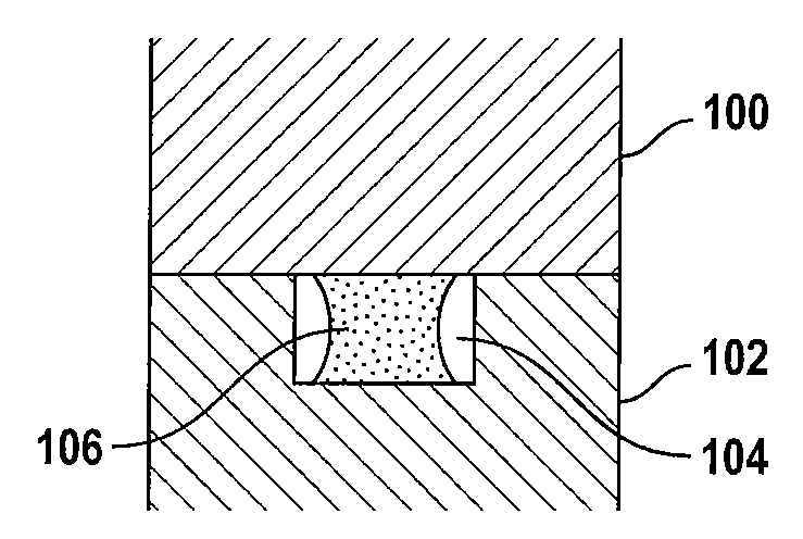
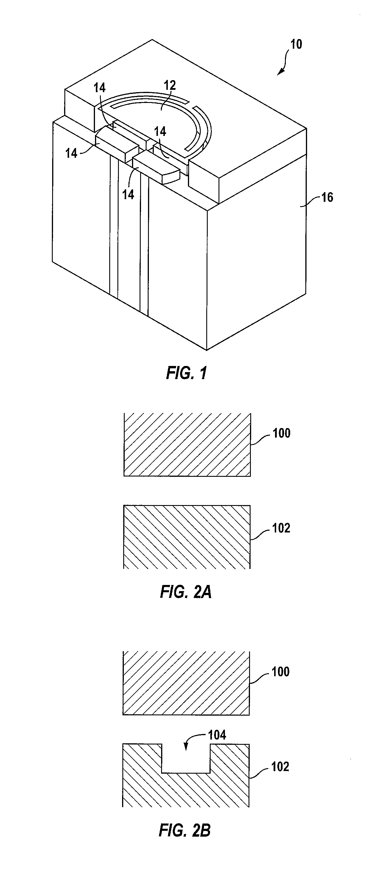
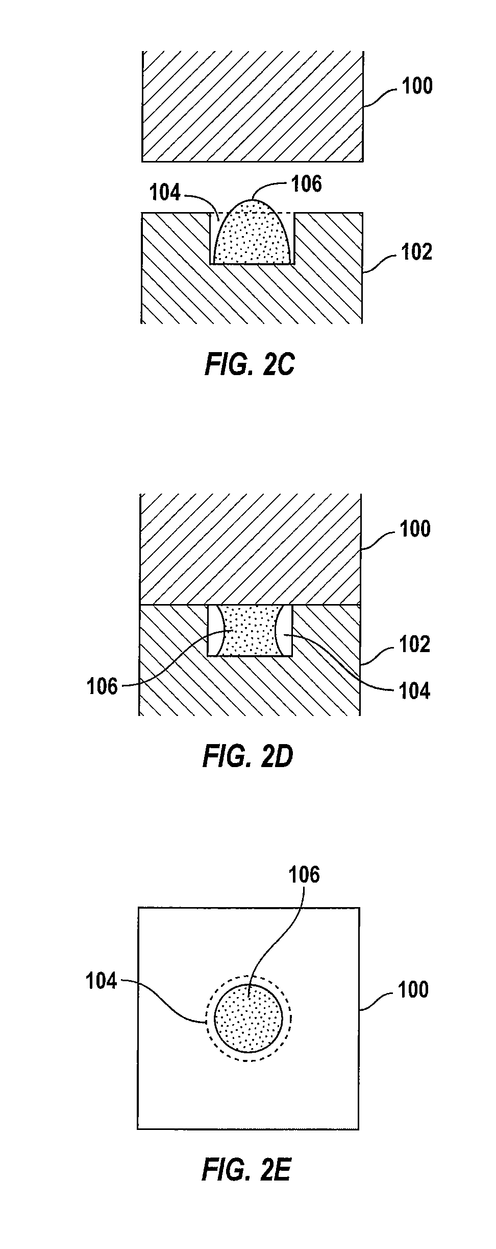
[0029]In accordance with the present invention, the distance between the surfaces of one or more parts bonded together is substantially reduced to a point of substantially zero-gap. Although, the following description is provided with reference to MEMS devices, it is understood that the present invention is equally applicable to other microstructures such as, semiconductor chips, micro-fluidic devices, and other types of hybrid structures in which there is substantive gain or advantage in having the parts bonded with a nearly zero (e.g., a few atomic layers) separation between the mating surfaces and in having the bonds localized. For example, this technique can be applied to the bonding of a multitude of integrated circuit chips to form a hybrid chip stack. It is also understood that the bonding surfaces may or may not be co-planar. Accordingly, the present invention applies as long as the bonding surfaces have matching shapes and can be brought to proximity of one another.
[0030]To...
PUM
| Property | Measurement | Unit |
|---|---|---|
| temperatures | aaaaa | aaaaa |
| temperatures | aaaaa | aaaaa |
| temperatures | aaaaa | aaaaa |
Abstract
Description
Claims
Application Information