Method and apparatus for improving water balance in fuel cell power unit

a fuel cell and water balance technology, applied in the direction of fuel cells, solid electrolyte fuel cells, electrical equipment, etc., can solve the problems of preventing their use, increasing the difficulty of use, and not being suitable for certain other applications, so as to prevent backflow from the combustion system, prevent the pressure of exhaust gas, and prevent the backflow of hot combustion gasses

Inactive Publication Date: 2008-05-15
BATTELLE MEMORIAL INST
View PDF7 Cites 9 Cited by
  • Summary
  • Abstract
  • Description
  • Claims
  • Application Information

AI Technical Summary

Benefits of technology

[0015]Preferably, but not meant to be limiting, the system is configured to heat the exhaust gas from the cathode side of the PEM fuel cell with the effluent gas from the combustion system in a recuperative heat exchanger prior to feeding the exhaust gas from the cathode side of the PEM fuel cell into the combustion system. This configuration assists both the synthesis gas forming reactions, by using waste heat to preheat the air fed to the combustor providing heat to drive the reactions, and assists the capture of water, by cooling the effluent gas from the combustion system, prior to condensing the water in the effluent gas.
[0016]Preferably, the present invention uses a series of check valves to route the various gasses in a manner that anticipates different operating conditions, and protects the various equipment used in the system. For example, and not meant to be limiting, the present invention preferably provides a check valve in the connection of the exhaust gas from the cathode side of the P

Problems solved by technology

While these systems have proven reliable and efficient in numerous applications, they are not suitable in certain other applications.
Additionally, issues related to the noise and vibration generated by internal combustion systems can prohibit their use.
Maintaining a positive water balance, where water condensed and recovered exceeds that being led to the process, becomes more and more difficult for high am

Method used


Image

  • Method and apparatus for improving water balance in fuel cell power unit
  • Method and apparatus for improving water balance in fuel cell power unit
  • Method and apparatus for improving water balance in fuel cell power unit

Examples


Embodiment Construction

[0024]For the purposes of promoting an understanding of the principles of the invention, reference will now be made to the embodiments illustrated in the drawings and specific language will be used to describe the same. It will nevertheless be understood that no limitations of the inventive scope is thereby intended, as the scope of this invention should be evaluated with reference to the claims appended hereto. Alterations and further modifications in the illustrated devices, and such further applications of the principles of the invention as illustrated herein are contemplated as would normally occur to one skilled in the art to which the invention relates.

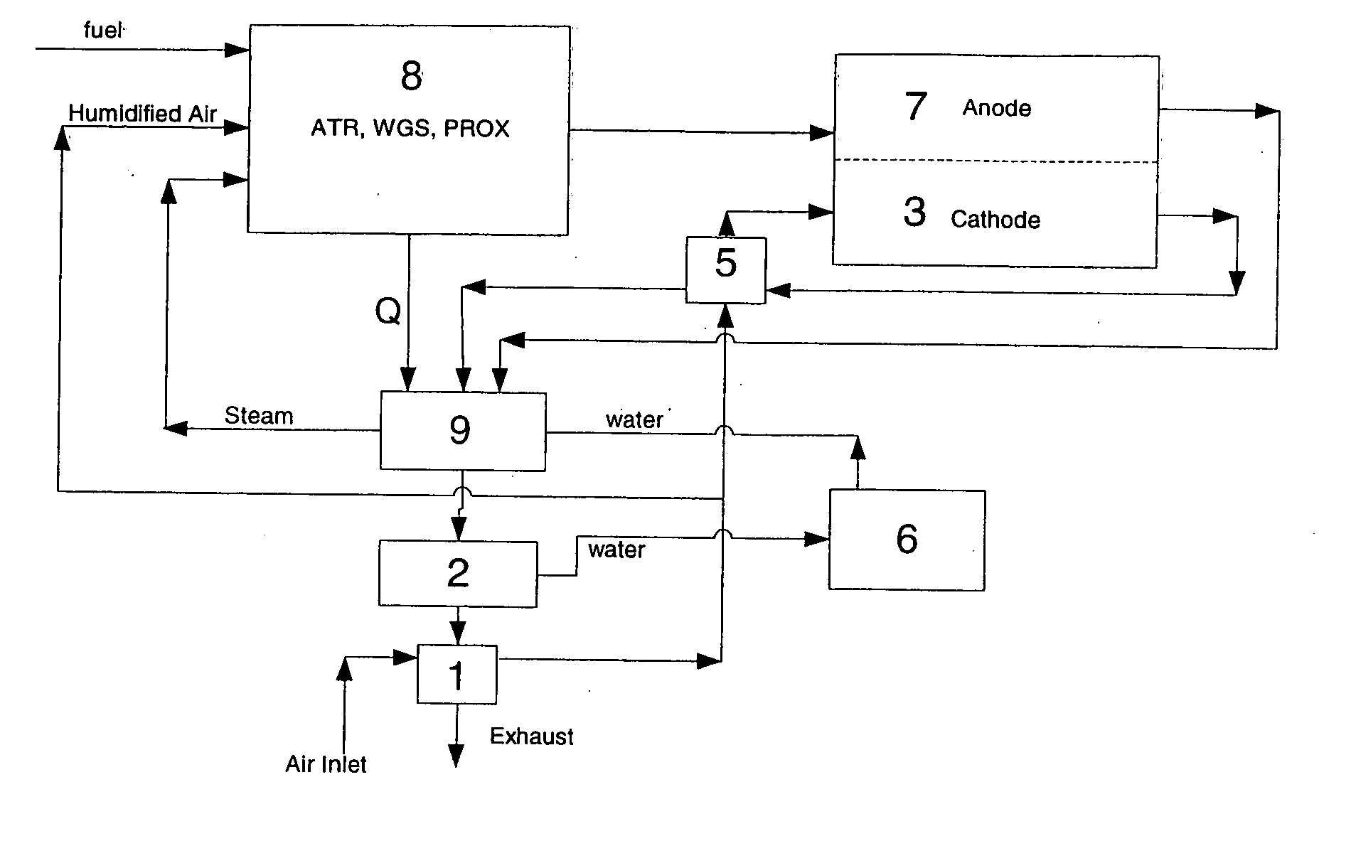
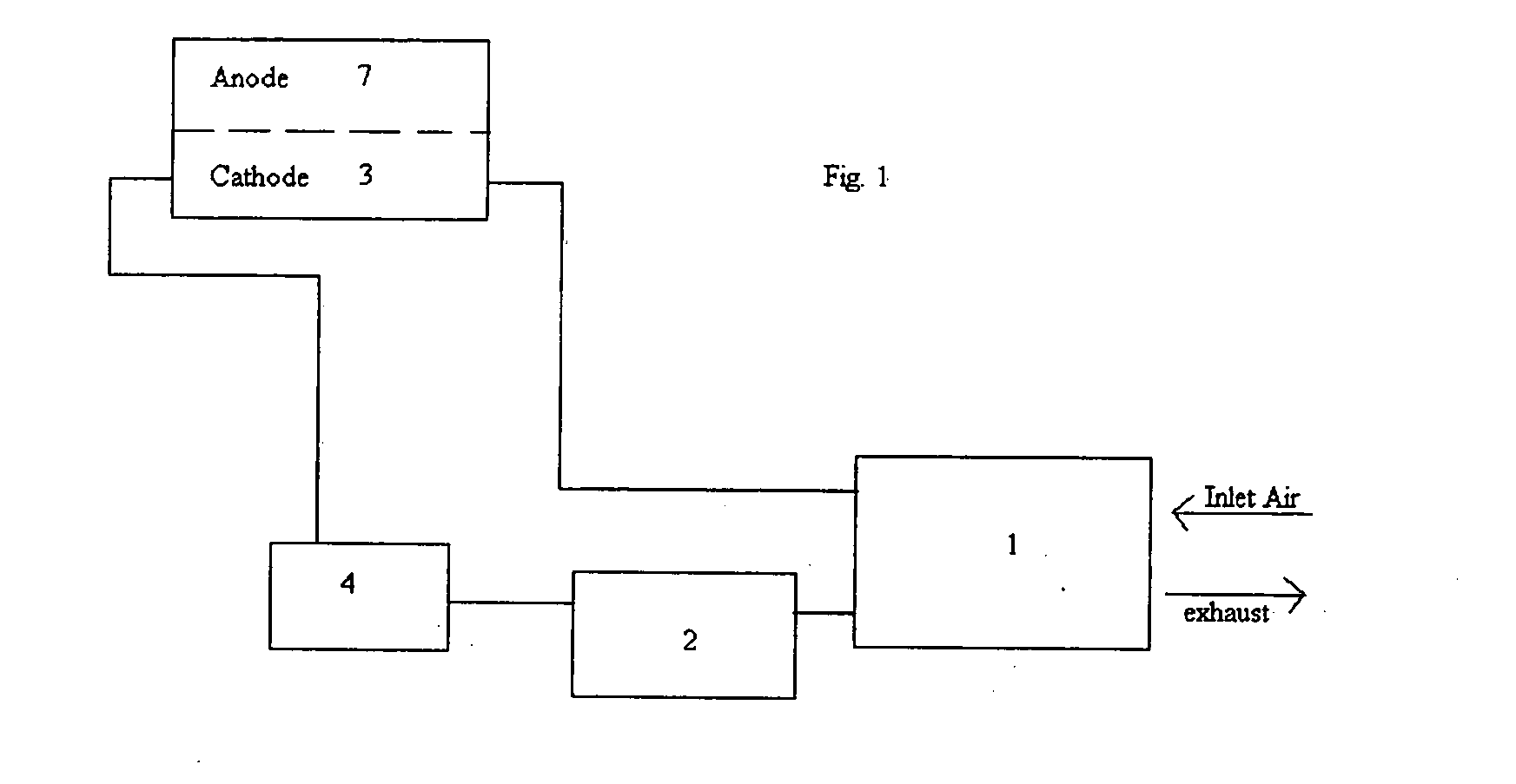
[0025]One form the present invention provides a humidifier coupling the reformer exhaust and the incoming cathode air. As shown in FIG. 1, inlet air enters a system at humidifier 1 where water is transferred from the uncondensed portion of the water in the effluent from the condenser 2 to the gas fed to the cathode side of a PEM...


PUM


Abstract

A method and apparatus for improving the water balance in the power unit by providing the exhaust gas from the cathode side of the PEM fuel cell as a feed gas to the combustion system of the steam reforming system, condensing at least a portion of water present in the effluent from the combustion system in a condenser, and then transferring water vapor from the uncondensed portion of the effluent from the condenser to the gas fed to the cathode side of the PEM fuel cell. Water from the exhaust gas from the cathode side of the PEM fuel cell is either captured in the condenser, or is reused in the feed gas of the cathode side of the PEM fuel cell. By humidifying the air fed into system with the water vapor present in the exhaust gas, water is not lost from the system. Instead, the air is being fed into the system is humidified with this water, which in turn allows the humidifier to operated at higher temperatures and/or use smaller radiators and fans and/or draw less parasitic power, thereby increasing overall system efficiency.

Description

[0001]Cross Reference to related applications (if any). (Related applications may be listed on an application data sheet, either instead of or together with being listed in the specification.)TECHNICAL FIELD[0002]This invention relates to polymer electrolyte membrane (PEM) fuel cells. More specifically, this invention relates to mobile power units using PEM fuel cells in conjunction with steam reforming fuel systems, and methods to improve the water balance in these systems.BACKGROUND OF THE INVENTION[0003]The need for mobile electrical power generation systems have traditionally been satisfied with generators powered by internal combustion engines fueled with gasoline or diesel fuel. While these systems have proven reliable and efficient in numerous applications, they are not suitable in certain other applications. For example, in many military applications the requirement that a single fuel source power both a vehicle and an auxiliary power system prevents the use of off-the-shelf...

Claims


Application Information

Patent Timeline
IPC IPC(8): H01M8/04H01M8/06
CPCH01M8/04014H01M8/04089H01M8/04141H01M8/04149Y02E60/50H01M8/0618H01M8/0662H01M8/0668H01M2008/1095H01M8/04164
Inventor WHYATT, GREG A.GEORGE, PAUL E.
Owner BATTELLE MEMORIAL INST
Why Eureka
Try Eureka