Apparatus for dehydrator and compressor combination skid and method of operation

a compressor and dehydrator technology, applied in the field of heat transfer systems, can solve the problems of ineffective removal of water vapour from natural gas, cost of fuel consumption, and eventually saturated water content of glycol itself, and achieve the effect of convenient manufactur

Inactive Publication Date: 2008-05-22
LEADER ENERGY SERVICES +1
View PDF3 Cites 1 Cited by
  • Summary
  • Abstract
  • Description
  • Claims
  • Application Information

AI Technical Summary

Benefits of technology

[0006]The present invention is directed toward a combination gas compressor unit and a glycol dehydrator unit wherein exhaust heat from the compressor's prime mover is transferred and used in the glycol dehydrator unit. One objective of the present invention is to provide an easy to manufacture and mobile apparatus that combines a gas compressor and a glycol dehydrator on one skid. Another objective of the present invention is to provide an apparatus that transfers the heat generated by a gas compressor unit to the glycol reboiler of the glycol dehydrator. Another objective of the present invention is to provide a glycol reboiler that does not burn fuel to achieve its requisite temperature. Yet another objective of the present invention is to provide a glycol dehydrator that is safer than fuel-fired dehydrators.

Problems solved by technology

However, the glycol itself eventually becomes saturated with water and ineffective at removing water vapour from natural gas.
There are several drawbacks associated with these units: safety issues; the cost of the fuel they consume; the negative environmental impact caused by their burning of fuel.
With respect to safety issues, a conventional glycol dehydration unit cannot even be placed on the same skid as a gas compressor unit because of the explosion hazards.
This greatly increases the cost of manufacturing and installation and makes it expensive to transport or move the units from place to place.

Method used


Image

  • Apparatus for dehydrator and compressor combination skid and method of operation
  • Apparatus for dehydrator and compressor combination skid and method of operation
  • Apparatus for dehydrator and compressor combination skid and method of operation

Examples


Embodiment Construction

[0014]The construction and operation of both gas compressors and glycol dehydration units is well known in the art and a detailed description of how they function and are used is therefore omitted from the present description. There are many commercially available units in the market today and the skilled technician will be familiar with the selection of units having a size, capacity and throughput appropriate to any particular installation. The present invention is intended to be adapted for use in most if not all such installations either as original equipment, as a retrofit or as a temporary replacement.

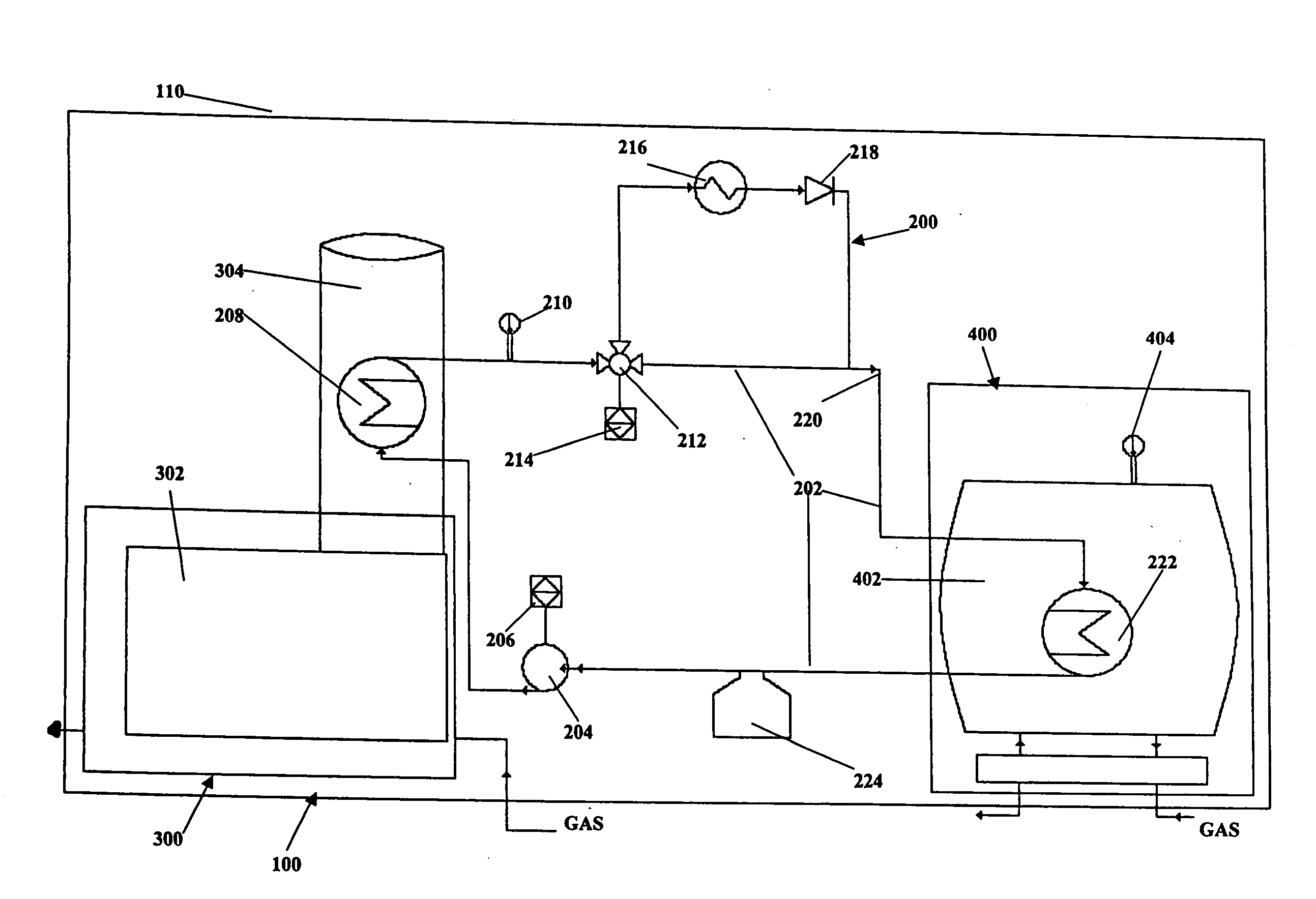
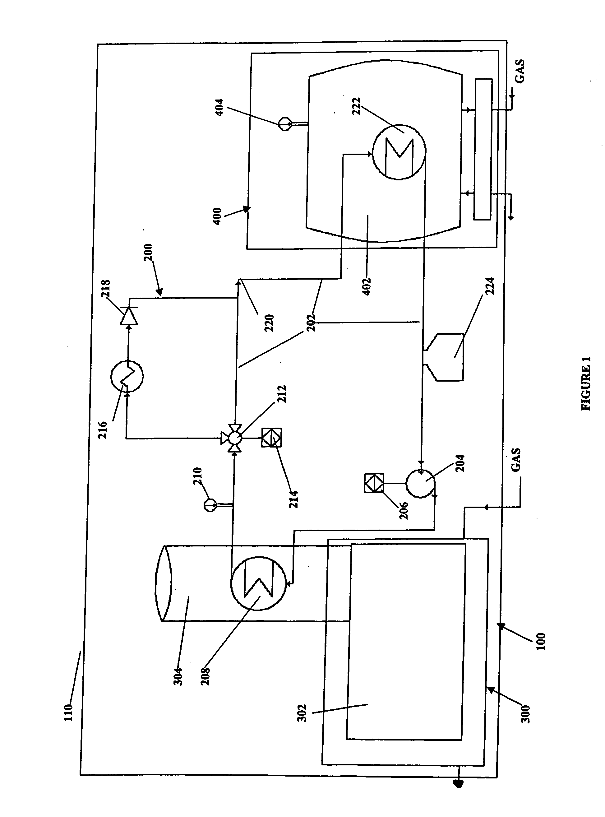
[0015]Referring to FIG. 1, the combined dehydration and compressor skid 100 of the present invention generally comprises a mounting skid 110, a closed loop fluid circuit 200 for a heat transfer fluid (also called “hot oil”), a gas compressor unit 300, and a glycol dehydrator unit 400. Compressor unit 300, glycol dehydrator 400 and fluid circuit 200 are mounted onto skid 110 which ...


PUM

PropertyMeasurementUnit
temperatureaaaaaaaaaa
temperaturesaaaaaaaaaa

Abstract

A method and apparatus for the dehydration of glycol, comprising a gas compressor unit including an engine which produces a flow of hot exhaust gas; a glycol dehydrator unit including a reboiler for heating and dehydrating the glycol; transferring heat from the exhaust gas to the reboiler to heat the glycol; and a support platform, wherein the gas compressor unit, the glycol dehydrator unit and the circuit for transferring heat are all supported on the support platform.

Description

CROSS-REFERENCE TO RELATED APPLICATIONS[0001]This application is a continuation-in-part of U.S. application Ser. No. 11 / 604,017, filed on Nov. 22, 2006, the disclosure of which is incorporated herein by reference.FIELD OF THE INVENTION[0002]The present invention relates generally to heat transfer systems and more specifically to the transfer of heat generated by a compressor motor for use in a dehydrator to remove water dissolved in a carrier fluid such as glycol.BACKGROUND OF THE INVENTION[0003]Gas compressors are commonly used to pressurize natural gas in order to facilitate the gas's movement through pipelines and other facilities.[0004]Glycol dehydration is a process that removes naturally occurring water, usually in the form of vapour, from natural gas, thereby preventing hydrate formation in and corrosion of gas pipelines. A glycol dehydration unit exposes natural gas to glycol. When natural gas comes in contact with glycol, the glycol removes water vapour from the natural gas...

Claims


Application Information

Patent Timeline
Patent Type & Authority Applications(United States)
IPC IPC(8): B01D19/00
CPCB01D53/263
Inventor THEIL, SWENBOWER, RICK
Owner LEADER ENERGY SERVICES
Why Eureka
Try Eureka