
Fuel cell heat exchange systems and methods

Active Publication Date: 2008-05-22
CERES INTPROP CO LTD
View PDF11 Cites 67 Cited by
  • Summary
  • Abstract
  • Description
  • Claims
  • Application Information

AI Technical Summary

Benefits of technology

[0016]In aspects of the invention, the order of the separate fluid feeds to the heat exchange elements, the arrangement and combination of heat exchange element(s) and / or the controllability of the fluid feeds allow for sufficient heat energy to be returned to the fuel cell system for sustained operation, and are advantageous and improve system operation and efficiency, whilst allowing for condensing of water vapour to occur independently, from at least one of the anode off-gas and from the cathode off-gas streams to maximise heat recovery for non-fuel cell system heat load use.
[0030]In a set-up according to an aspect of the invention of at least two heat exchange elements, these can be combined into the same unit, thus providing a more cost effective and efficient unit. Further, where there are reduced fluid connections, simpler packaging and a lighter overall unit can be achieved.

Problems solved by technology

In order to operate, the fuel cell consumes fuel and consumes oxygen in the air in the electrochemical reaction.

Method used


Image

  • Fuel cell heat exchange systems and methods
  • Fuel cell heat exchange systems and methods
  • Fuel cell heat exchange systems and methods

Examples


Embodiment Construction

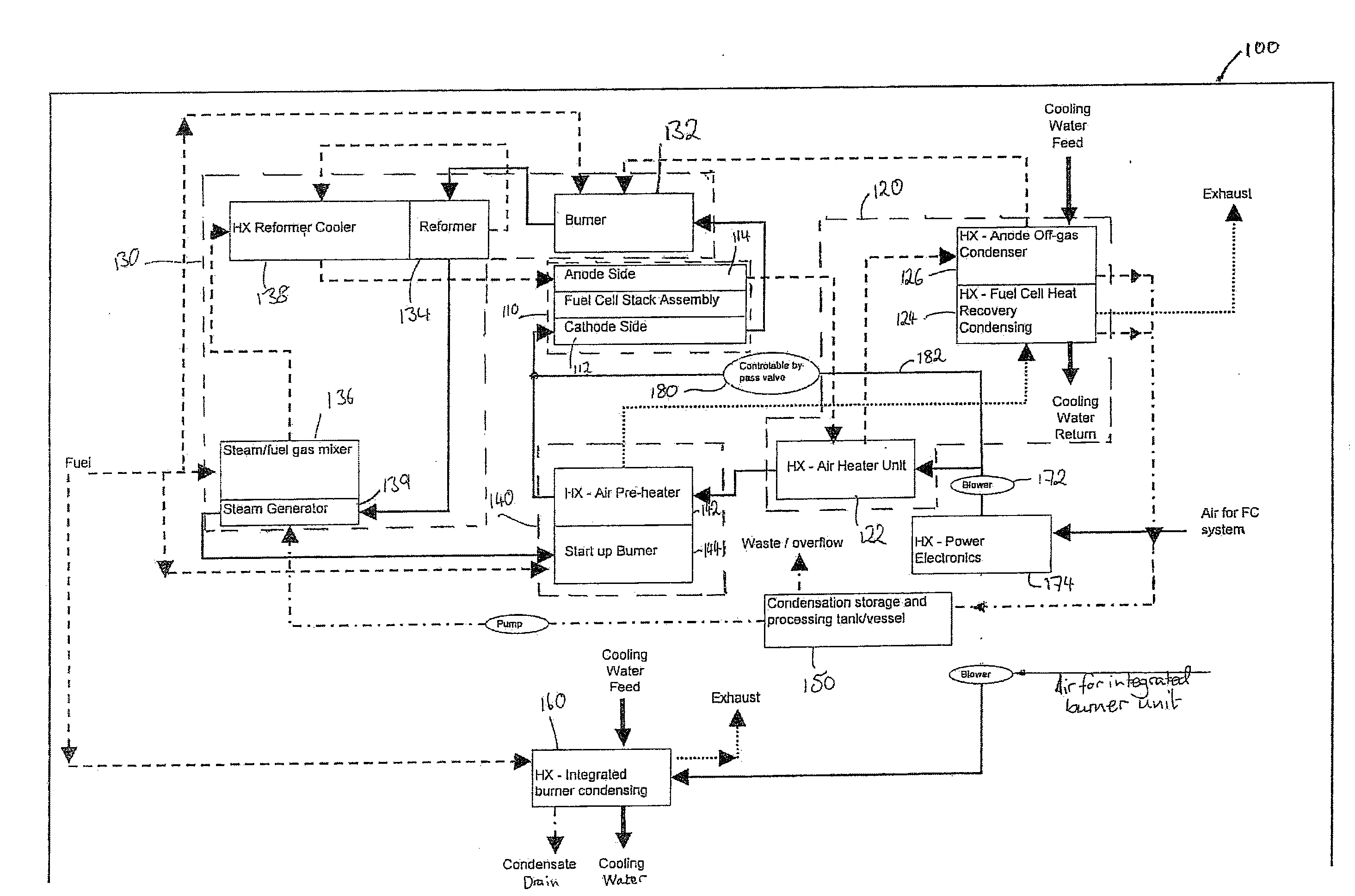
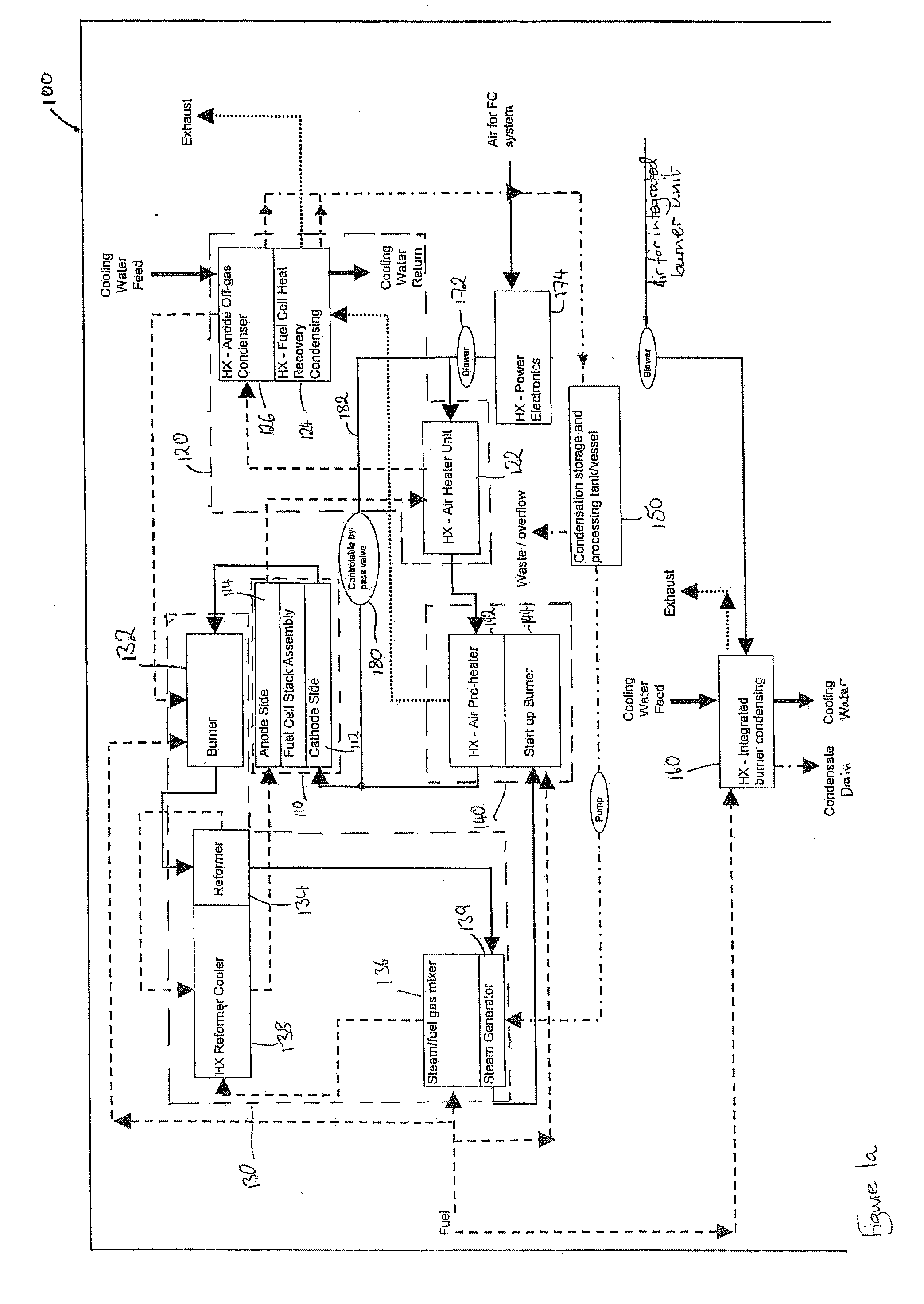
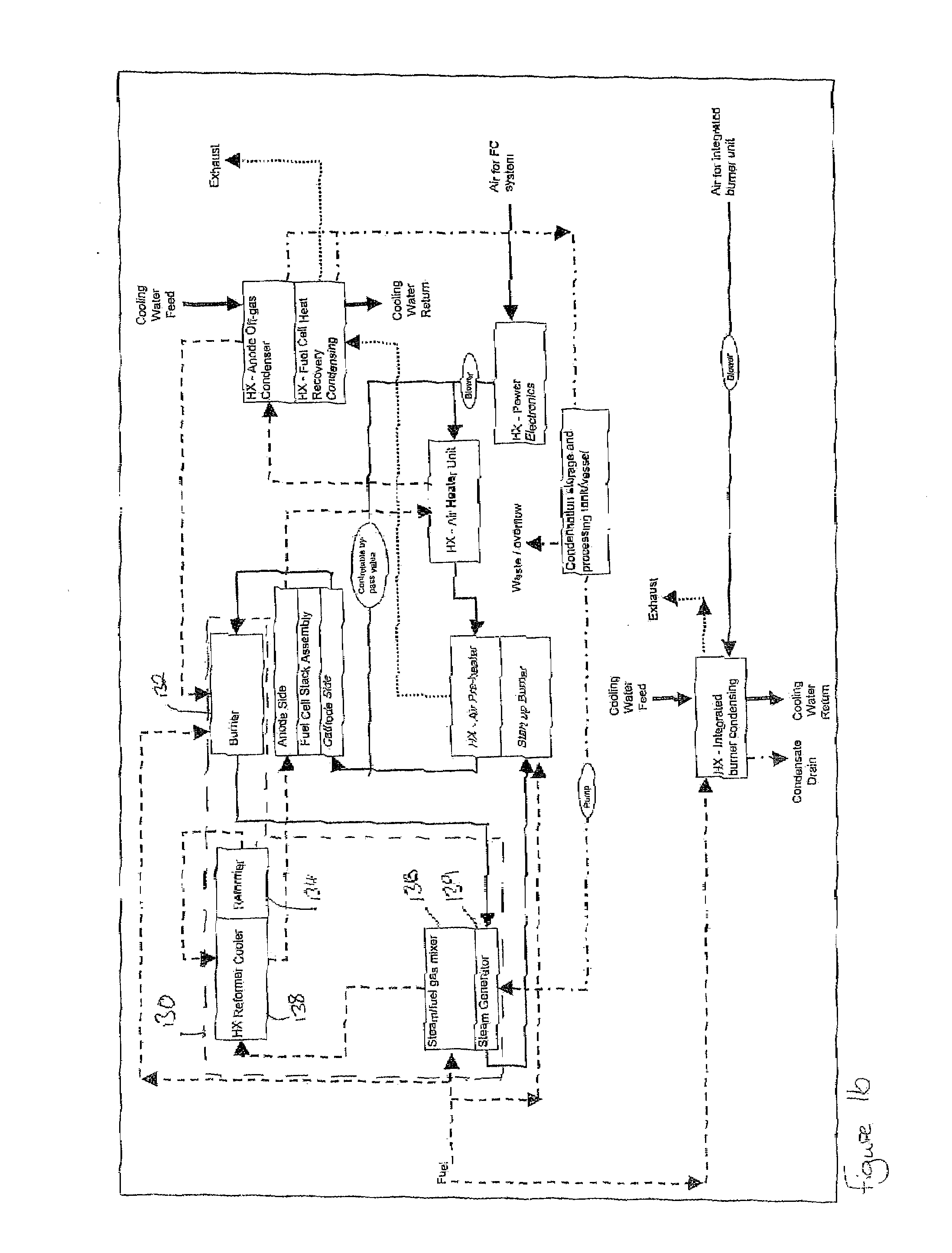
[0045]FIG. 1a shows a fuel cell system 100 including a heat exchange system 120 according to an embodiment of the invention. The fuel cell system 100 includes a fuel cell stack assembly 110 and a heat exchange system 120. The fuel cell system 100 also includes a burner / reformer unit 130, a start-up heating unit 140, and a condensation water storage tank 150.

[0046]With reference to FIG. 1a, fluid flow paths undertaken by the oxygen gas (e.g. air) and the fuel gas for the operation of the fuel cell system are shown.

[0047]Firstly, the air-side feed system will be described. Oxygen containing gas, commonly air, is supplied to the fuel cell system 100 from the environment via an air filter unit (not shown) and a mechanical air movement device, in the present embodiment a variable speed air blower 172—with the blower speed being controlled by a system control unit (not shown). The air filter unit can be mounted on a frame surrounding the system. The air is drawn through the unit to the ai...


PUM


Abstract

A system and method are provided for exchanging heat in fuel cell systems (100) in which the anode and cathode off-gases are provided with separated flow paths. In one embodiment, where a fuel cell stack (110) has separate anode and cathode off-gas flow paths, separate anode off-gas from the at least one fuel cell stack (110) and at least one heat transfer fluid are passed through a first heat exchange element (126) to exchange heat between the anode off-gas and the heat transfer fluid. The cathode off-gas exiting the at least one fuel cell stack is then combined with the anode off-gas from the heat exchange element (126) in a burner and burned.

Description

FIELD OF THE INVENTION[0001]The present invention relates to energy management within fuel cell systems. In particular, the present invention relates to heat exchange systems and methods within fuel cell systems.BACKGROUND OF THE INVENTION[0002]Solid-Oxide Fuel Cell (SOFC) systems operate efficiently by converting the energy contained in a fuel stream into usable heat and electricity. Heat recovery in SOFC systems is commonly achieved by the use of heat exchangers (for example, shell and tube, plate and fin and micro channel) in a variety of flow configurations (multi-stream, counter flow, co-flow, cross flow). Some of the fluid streams in the system are liquid and some are gas, of which some contain water vapour. The SOFC system efficiency can be derived from comparing the potential energy contained in the fuel stream entering the system to the total usable heat and power produced by the system and available to the user. Overall SOFC system efficiency is important as it impacts on ...

Claims


Application Information

Patent Timeline
IPC IPC(8): H01M8/04
CPCH01M8/04014H01M8/04029H01M8/04067H01M8/04156H01M8/0618Y02T90/32H01M2008/1293H01M2250/20Y02E60/50Y02E60/525H01M8/0662Y02T90/40H01M8/06H01M8/04F28D1/047F28F1/06H01M8/12
Inventor DEVRIENDT, JAMESMORGAN, ROBERTBARNARD, PAULLEAH, ROBERT
Owner CERES INTPROP CO LTD
Learn More