

Reflective optical system for a photolithography scanner field projector
a projector and projector technology, applied in the field of field projection systems for photolithography, can solve the problems of increasing the loss of light, unable to make projection optics using transparent lenses, and producing still smaller features
- Summary
- Abstract
- Description
- Claims
- Application Information
AI Technical Summary
Benefits of technology
Problems solved by technology
Method used
Image

Examples
first embodiment
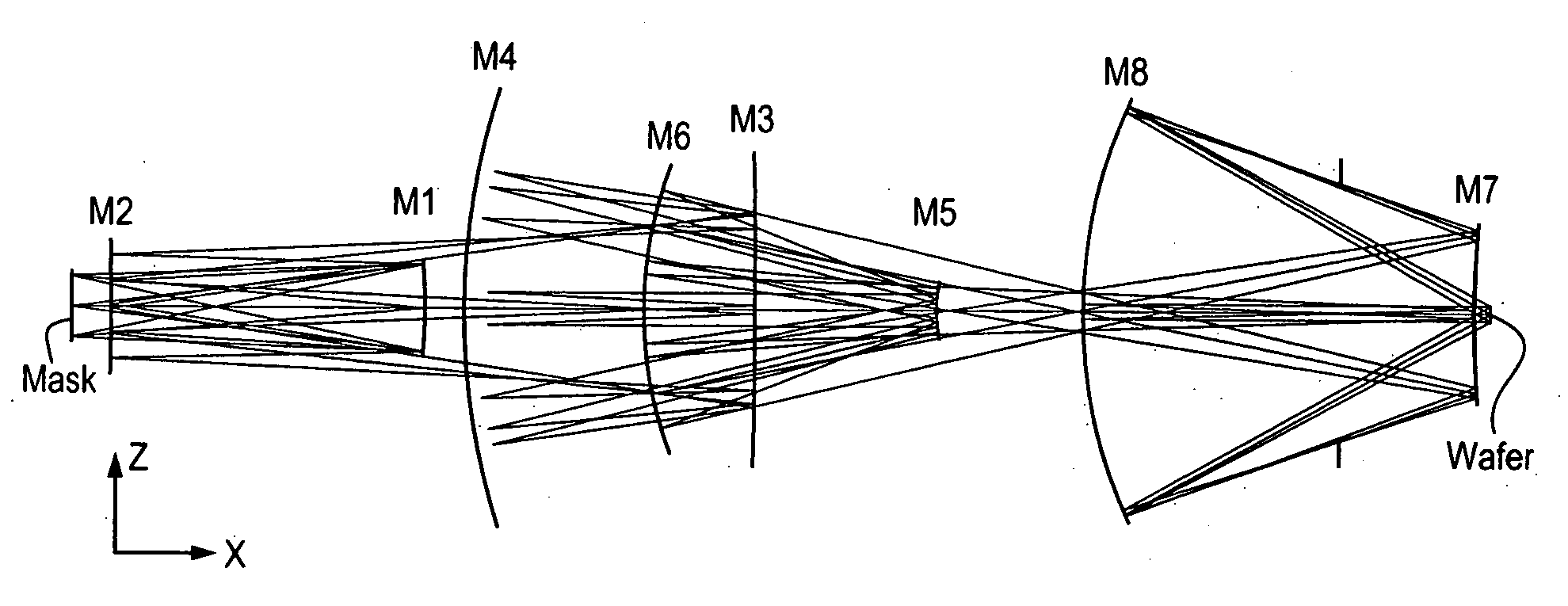
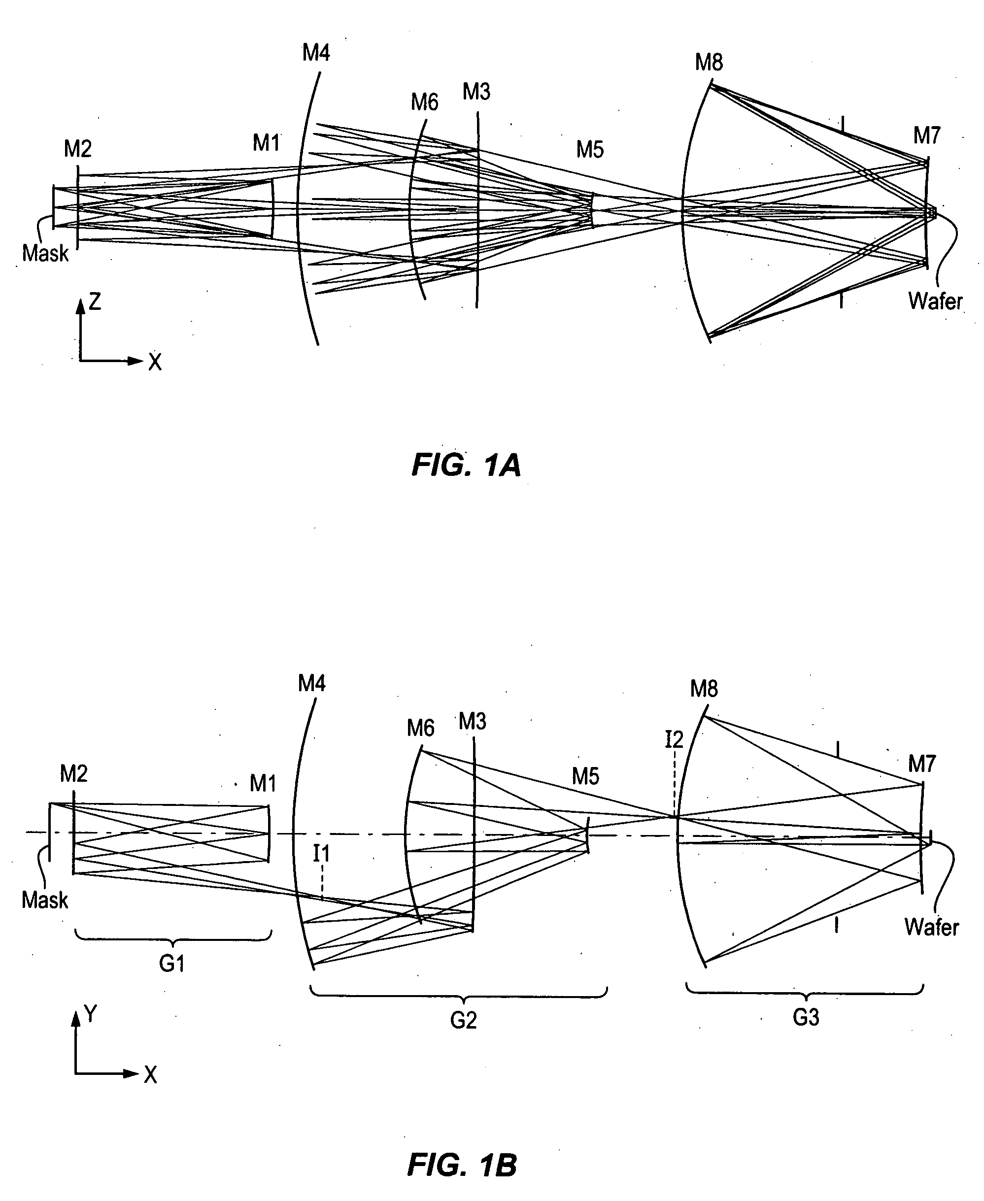
[0035]In the projection system of FIGS. 1A and 1B, from long conjugate to short conjugate, the first mirror is concave, the second convex, the third concave, the fourth concave, the fifth convex, the sixth concave, the seventh convex, and the eighth concave. Denoting a concave mirror with a ‘P’ (positive optical power) and a convex mirror with an ‘N’ (negative optical power), the configuration of the first embodiment may be described as “PNPPNPNP”.
[0036]Mirrors M1 and M2 work together as a first imaging group G1. Group G1 forms an intermediate image I1 of the mask after mirror M2. Mirrors M3, M4, M5, and M6 form another imaging group G2 to form a second intermediate image I2 of the first intermediate image between M6 and M7. This intermediate image is relayed by the third imaging group G3 consisting of mirrors M7 and M8 onto the wafer.
[0037]Group G3 relays the second intermediate image 12 formed by Group G2 to the wafer at the proper reduction, which in this example is a fourfold re...
third embodiment
[0061]FIG. 15 shows the present invention. FIG. 15 shows the system in the x-z plane. The reflective optical system of FIG. 15 is also an obscured eight-mirror system design that can achieve a numerical aperture of 0.50 with a ring field width between 1-2 mm. The mask is at the far left of the diagram and the wafer is at the far right. The light source and collection optics to illuminate the mask are again not shown. Of the eight mirrors, mirrors M7 and M8 again have a small obscuration in the form of a hole through the surface of the mirror.
[0062]In the projection system of FIG. 15, from long conjugate to short conjugate, the first mirror is concave, the second concave, the third convex, the fourth concave, the fifth convex, the sixth concave, the seventh convex, and the eighth concave. Denoting a concave mirror with a ‘P’ (positive optical power) and a convex mirror with an ‘N’ (negative optical power), the configuration of the third embodiment may be described as “PPNPNPNP”.
[0063...
PUM
| Property | Measurement | Unit |
|---|---|---|
| angle of incidence | aaaaa | aaaaa |
| angles of incidence | aaaaa | aaaaa |
| wavelength | aaaaa | aaaaa |
Abstract
Description
Claims
Application Information