Eureka AIR delivers breakthrough ideas for toughest innovation challenges, trusted by R&D personnel around the world.

Fuel injection and mixing systems having piezoelectric elements and methods of using the same

a piezoelectric element and mixing system technology, applied in the direction of hydrogen/synthetic gas production, combustion air/fuel air treatment, hydrogen/synthetic gas production, etc., can solve the problems of high manufacturing cost, fuel cell industry facing several critical challenges, and preventing them from being accepted for a wide variety of applications, so as to improve the mixing and uniformity of feed streams, minimize pressure loss, and optimize the effect of injector performan

Active Publication Date: 2008-05-29
DELAVAN
View PDF29 Cites 17 Cited by
  • Summary
  • Abstract
  • Description
  • Claims
  • Application Information

AI Technical Summary

Benefits of technology

[0014]In accordance with a further aspect of the invention, the fuel injection and mixing system is preferably designed to directly operate with fuel processors, such as steam reformers, catalytic partial oxidation reformers, and auto-thermal reformers. The injection system has the ability to effectively vaporize liquid fuels and to achieve complete mixing within a short distance at various operating conditions, particularly at relatively low fuel flow rates.
[0019]In accordance with another aspect of the invention, the gas swirlers used in association with various embodiments of the present invention are designed to direct heated gas streams, such as streams including steam and / or air, in such a way as to interact with the fuel droplets in order to provide additional atomization and mixing. The gas swirlers can also be adapted and configured to direct gas jets toward the atomizing face to wipe the atomizing face and to break up any fuel which may amass on the atomizing face. The gas swirlers can also prevent droplets from adhering to the chamber walls or accumulating near corner areas of the chamber, in order to protect chamber walls from carbon formation.
[0021]In accordance with one aspect of the invention, a mixing chamber embodiment is provided that utilizes a flow stabilizing mixer that anchors the swirling spray around the center body and keeps the spray from fluttering or biasing towards one side. The mixer may contain a center body that has a pointed nose and tail section with helical vanes positioned in the middle section. The helical vanes can be arranged to provide either co-swirling or counter-swirling flows relative to the swirl direction of the spray. Although applicants have discovered that both co-swirling and counter-swirling mixers work well, applicants have found that co-swirling mixers seem to perform better in keeping the chamber wall surface clean while counter-swirling mixers provide superior vapor mixing and uniformity. The swirl strength of the mixer can be adjusted so that vortices and central recirculation zones are minimized or canceled out downstream of the mixer. A proper distance is preferably maintained between the injector and the mixer to minimize reversed flow and excess fuel accumulation in the upstream region of the mixer.
[0023]In accordance with still another aspect of the invention, a mixing chamber embodiment may be provided including a stack of perforated plates to further enhance the mixing and uniformity of the feed streams prior to entering the reactor. The perforated plates can be very effective in redistributing the fuel / gas mixture evenly near the reactor entrance area. The porosity, spacing, alignment, and number of the perforated plates can be selected to minimize the pressure loss across the mixing chamber.
[0024]In accordance with another aspect of the invention, a mixing chamber embodiment is provided wherein the midsection of the inner wall of the mixing chamber transitions from a circular shape into a contour resembling a star shape with rounded comers. The outer “fingers” or lobes of the inner wall diverge from the centerline (moving downstream), while the contour in the central “hub” area of the inner wall converges. This configuration effectively mixes and evens the flow field within a very short distance downstream, typically within a distance equal to approximately two diameters of the mixing chamber. In accordance with a further aspect of the invention, the mixing swirlers and perforated plates can be interchangeably installed and even installed simultaneously in series in the mixing chamber to optimize the injector performance.

Problems solved by technology

Although various types of fuel cells have been installed for commercial use, high manufacturing costs have largely prohibited them from being accepted for a wide variety of applications.
In addition to high manufacturing cost, the fuel cell industry is faced with several critical challenges that must be resolved before fuel cell systems can be fully commercialized for wide spread power generation applications.
Current state-of-the-art fuel processors are limited to using gaseous fuels, such as natural gas, hydrogen and liquefied petroleum gas (LPG).
Currently, liquid fuel processing technology is not yet viable for commercial applications in SOFC systems.
One technical barrier for liquid fuel processing is reactor durability.
The performance of the reforming catalysts quickly deteriorates as a result of carbon deposition, sulfur poisoning and loss of precious metals due to sintering or evaporation at high temperatures.
Poor feed stream preparation such as inadequate atomization, wall impingement, and non-uniform mixing can easily lead to local conditions that favor carbon deposition and formation of hot spots in the reactor.
In most mobile APU applications, there are very limited supply pressures available for liquid atomization and feed stream mixing, making it especially challenging for the design and development of fuel injection and mixing systems.

Method used


Image

  • Fuel injection and mixing systems having piezoelectric elements and methods of using the same
  • Fuel injection and mixing systems having piezoelectric elements and methods of using the same
  • Fuel injection and mixing systems having piezoelectric elements and methods of using the same

Examples


Embodiment Construction

[0039]Reference will now be made in detail to the present preferred embodiments of the invention, examples of which are illustrated in the accompanying drawings. The method and corresponding steps of the invention will be described in conjunction with the detailed description of the system.

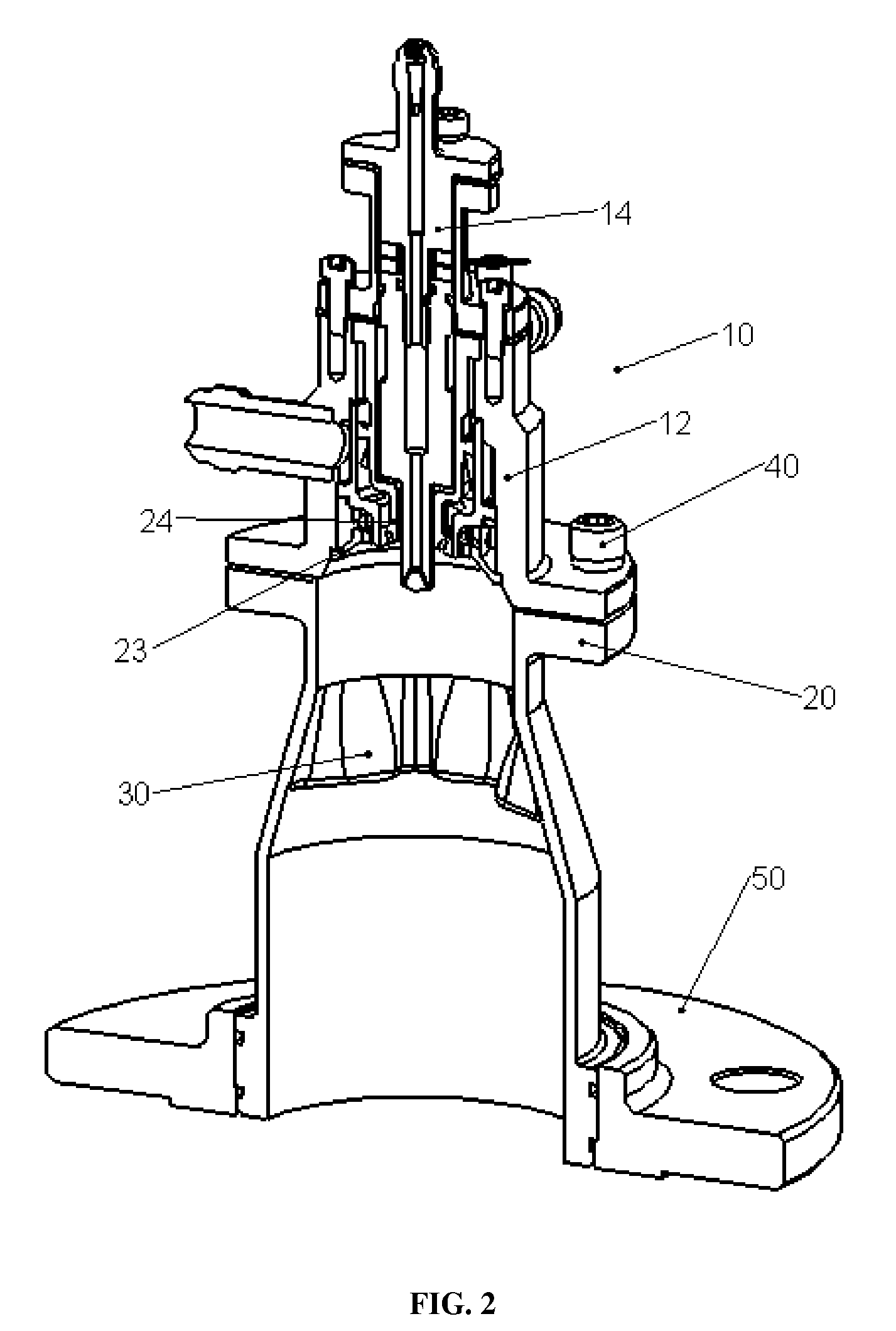
[0040]For purpose of explanation and illustration, and not limitation, a partial view of an exemplary embodiment of a fuel injection and mixing system in accordance with the invention is shown in FIG. 2 and is designated generally by reference character 10. Other embodiments of a fuel injection and mixing system in accordance with the invention, or aspects thereof, are provided in FIGS. 1 and 3-11, as will be described.

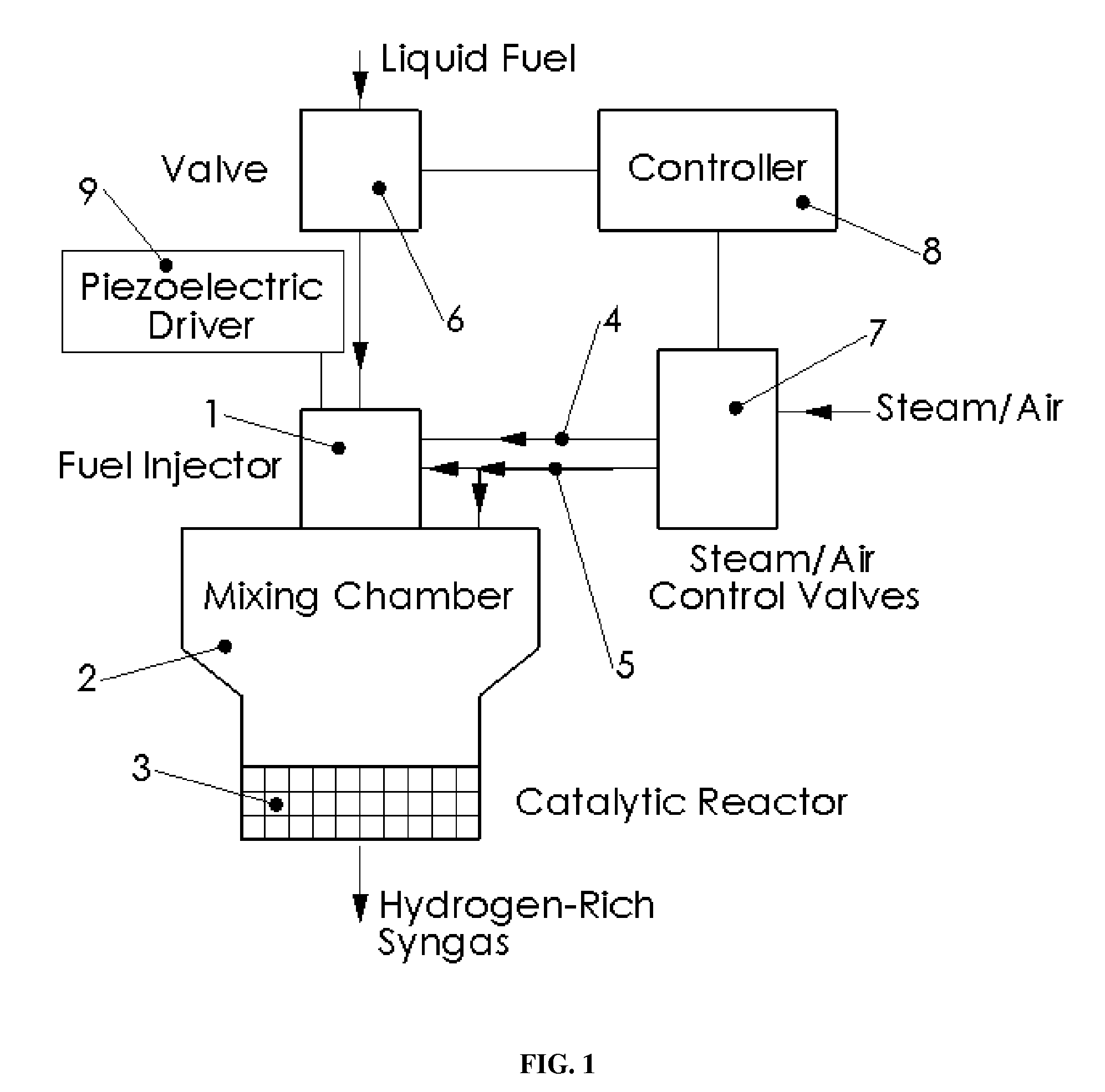
[0041]In accordance with the invention, a fuel injection and mixing system is provided that is suitable for use with various types of fuel reformers. Preferably, the system includes a piezoelectric injector for delivering atomized fuel, gas swirler(s), such as a steam and / or an air ...


PUM

PropertyMeasurementUnit
Mass flow rateaaaaaaaaaa
Pressureaaaaaaaaaa
Flow rateaaaaaaaaaa

Abstract

A fuel injection and mixing system is provided that is suitable for use with various types of fuel reformers. Preferably, the system includes a piezoelectric injector for delivering atomized fuel, a gas swirler, such as a steam swirler and / or an air swirler, a mixing chamber and a flow mixing device. The system utilizes ultrasonic vibrations to achieve fuel atomization. The fuel injection and mixing system can be used with a variety of fuel reformers and fuel cells, such as SOFC fuel cells.

Description

CROSS-REFERENCE TO RELATED APPLICATIONS[0001]This application claims the benefit of priority of U.S. Provisional Application Ser. No. 60 / 791,602 filed Apr. 12, 2006. This application is incorporated by reference herein in its entirety.FIELD OF THE INVENTION[0002]The present invention relates to fuel injection and mixing systems. Particularly, the present invention is directed to an integrated fuel injection and mixing system for fuel reformers or fuel processors to generate hydrogen-rich gas, such as for fuel cell applications.BACKGROUND OF THE INVENTION[0003]Fuel cells are an emerging technology that can significantly improve energy efficiency and energy security. Fuel cell technology can provide environmentally friendly electrical energy, producing far fewer harmful pollutants and lower levels of noise than conventional power generation systems. Although various types of fuel cells have been installed for commercial use, high manufacturing costs have largely prohibited them from b...

Claims


Application Information

Patent Timeline
IPC IPC(8): B05B17/06
CPCC01B3/38Y02E60/525C01B2203/0244C01B2203/0261C01B2203/066C01B2203/1276F02M25/12F02M27/08F02M31/18H01M8/04201H01M8/0618H01M2008/1293Y02T10/121Y02T10/126Y02E60/50C01B2203/0233Y02T10/12
Inventor MAO, CHIEN-PEISHORT, JOHNKLEMM, JIMABBOTT, ROYCEOVERMAN, NICKPACK, SPENCERWINEBRENNER, AUDRA
Owner DELAVAN
Why Eureka
Eureka Blog
Learn More