Pressure swing CVI/CVD

a technology of pressure swing and cvi, which is applied in the direction of coating, chemical vapor deposition coating, metallic material coating process, etc., can solve the problems of clogging pores, destroying the whole process, and both chemical vapor deposition and chemical vapor infiltration are extremely complex processes

Inactive Publication Date: 2008-05-29
HONEYWELL INT INC
View PDF9 Cites 27 Cited by
  • Summary
  • Abstract
  • Description
  • Claims
  • Application Information

AI Technical Summary

Benefits of technology

[0014]The present invention employs low pressures in a way that enables the length of the CVI / CVD process to be dramatically shortened. In accordance with the present invention, the initial pressure is no greater than 50 torr, and that low pressure is reduced even lower as the reaction proceeds, finishing as low as 10 torr. The “low→lower” approach of the present invention provides a more constant rate of densification as compared to a process which uses a constant, high pressure. This approach enables attainment of a target increased density in a carbon fiber preform much more quickly than known processes. This invention may set a programmed pressure swing throughout the CVI / CVD run in order to provide a linear increase in density. Alternatively, this invention may make step changes in pressure during the course of the densification process to enhance the rate of densification. This invention reduces the number of cycles and the required intermediate machining steps necessary to densify preforms.
[0018]In the method of the present invention, linear flow of the gaseous deposable carbon material may conveniently be directed from the bottom to the top of the reaction zone. The reactant gas can be methane or natural gas, possibly further including propane gas. In such a case, the ratio by volume of methane or natural gas to propane gas will typically be greater than 5:1. The reactant gas may be free of admixed inert gas. In carrying out the present densification process, multiple porous carbon fiber preforms may be adjusted apart from one another in such a way as to provide widths of equal spacing therebetween. The temperature in the reaction zone can conveniently be set in the range 1000° C. to 1200° C., although other high temperatures can be used. Preferably, the linear flow of the deposition gas is adjusted to have a flow rate such that no more than 5% of the disposable material in the flowing gas is deposited into the porous carbon fiber preform.

Problems solved by technology

Both chemical vapor deposition as well as chemical vapor infiltration are extremely complex processes.
If decomposition of the volatile or gaseous starting compounds, and formation of the solid phase, occurs in the gas phase and on the surface of the porous structure in or near the entrances of the pores, the pores become clogged.
The pores are then not filled, which defeats the whole aim of the process.
Here, however, only very low pressures or partial pressures of educt gases can be used, when necessary with addition of inert or dilution gases, so that extremely long infiltration times are required.
Due to the low partial pressures, extremely long infiltration times of up to several weeks are required.
Significant disadvantages of this method include the cost of the apparatus as well as the filtration times, which are still very long.
A disadvantage of this method is the very high gas throughput necessary for cooling.
The low yield of deposited material entails long production times. Much equipment is needed for the heating.
After a certain level of pore filling however, the streaming through of the porous structure becomes more difficult.
The disadvantage of such a method is the complicated reactor construction.

Method used


Image

  • Pressure swing CVI/CVD
  • Pressure swing CVI/CVD
  • Pressure swing CVI/CVD

Examples


Embodiment Construction

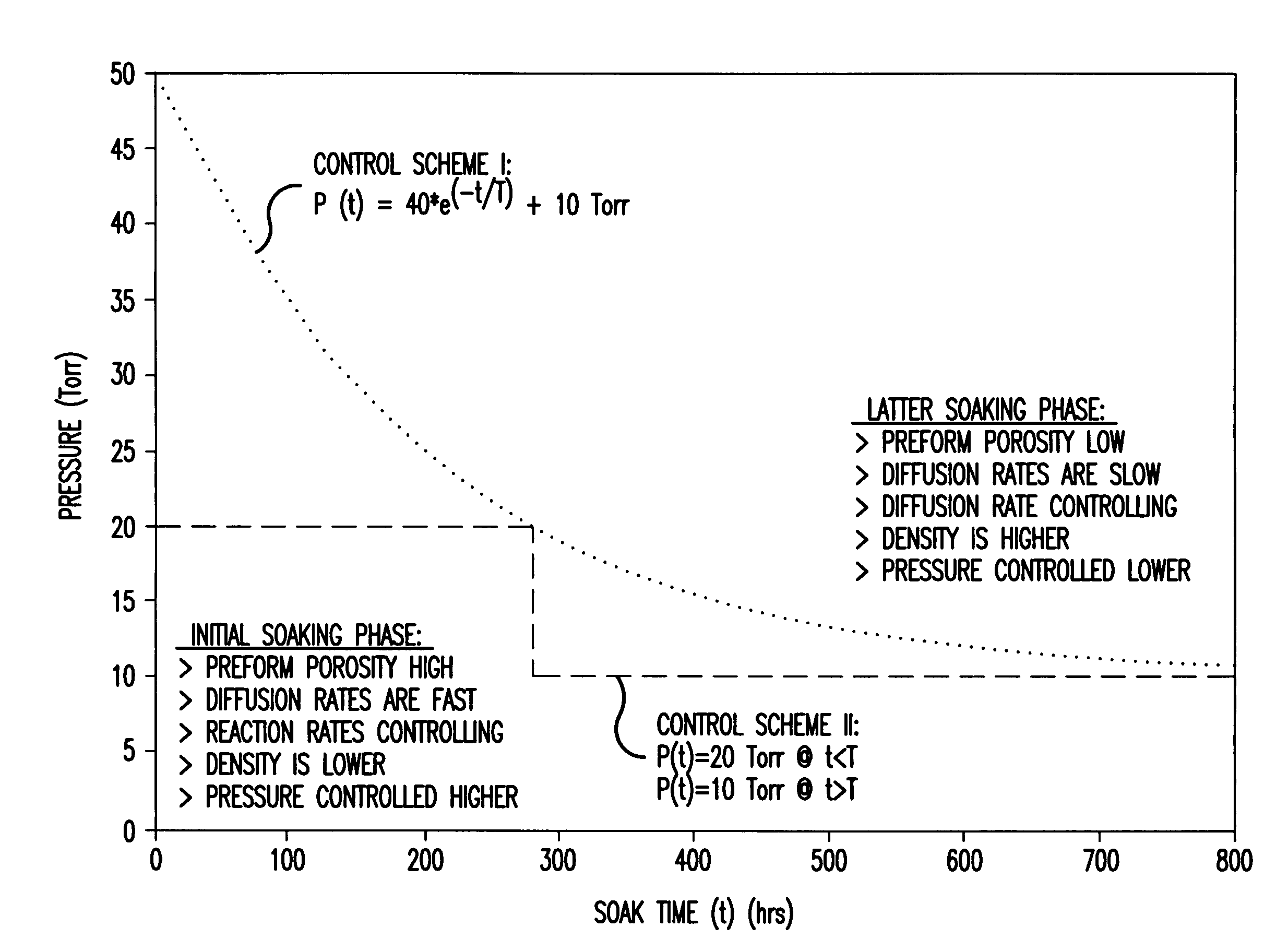
[0027]According to the present invention, low temperatures can be employed for vapor infiltration. According to a preferred embodiment, temperatures in the range of 1000 to 1200° C. are set in the reaction zone for vapor infiltration of carbon fiber preforms. Gas is passed over the porous structure which comprises a by-product generated during vapor infiltration. Preferably higher hydrocarbon enriching gases such as propane are added to the methane or natural gas primary reactant gas for vapor infiltration of the carbon fiber preform. The volume ratio of methane or natural gas to added enriching gas is typically more that 5:1.

[0028]In accordance with the present invention, low pressures or partial pressures must be used, especially pressures of at most 50 torr and as low as 10 torr.

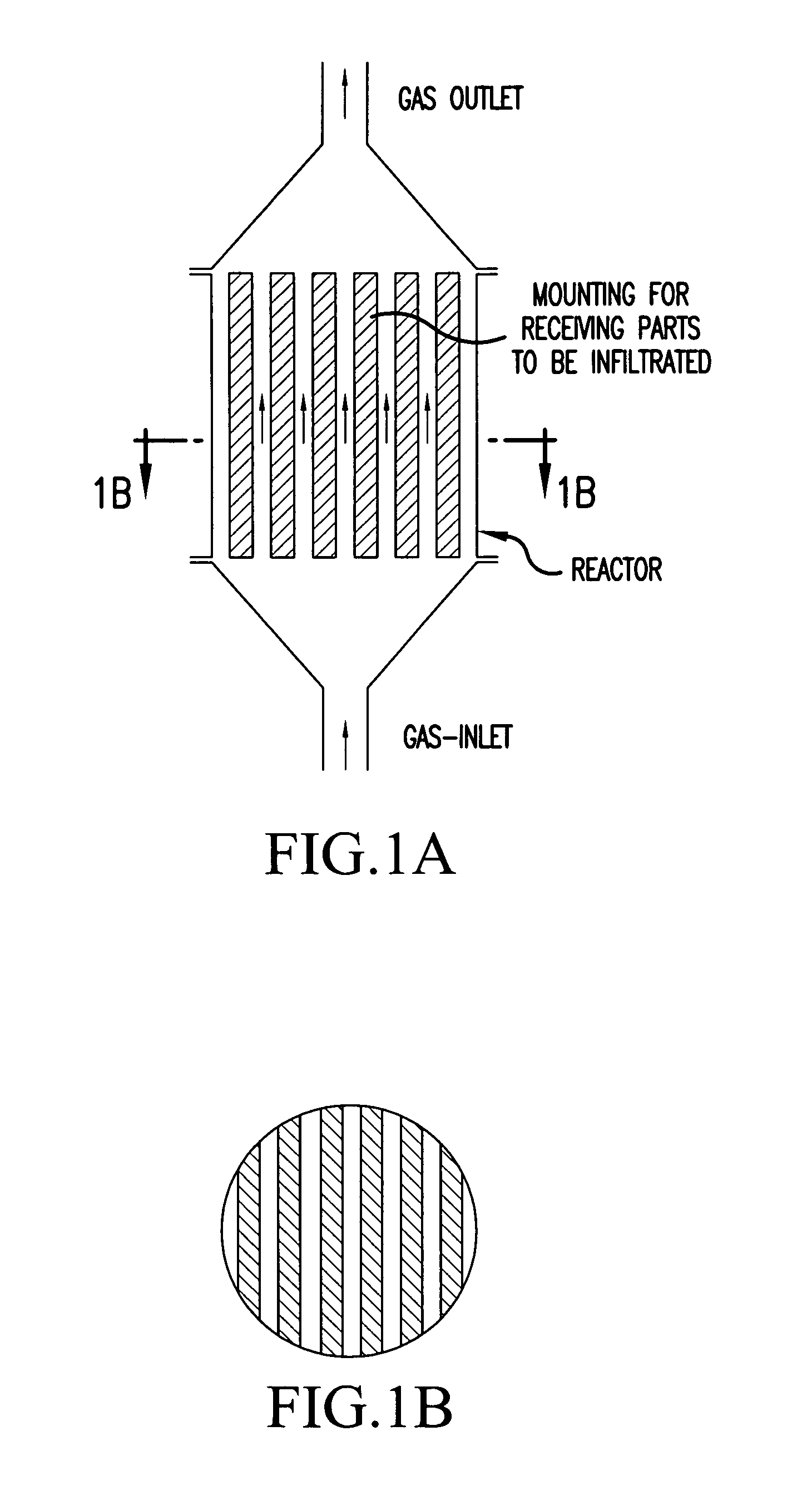
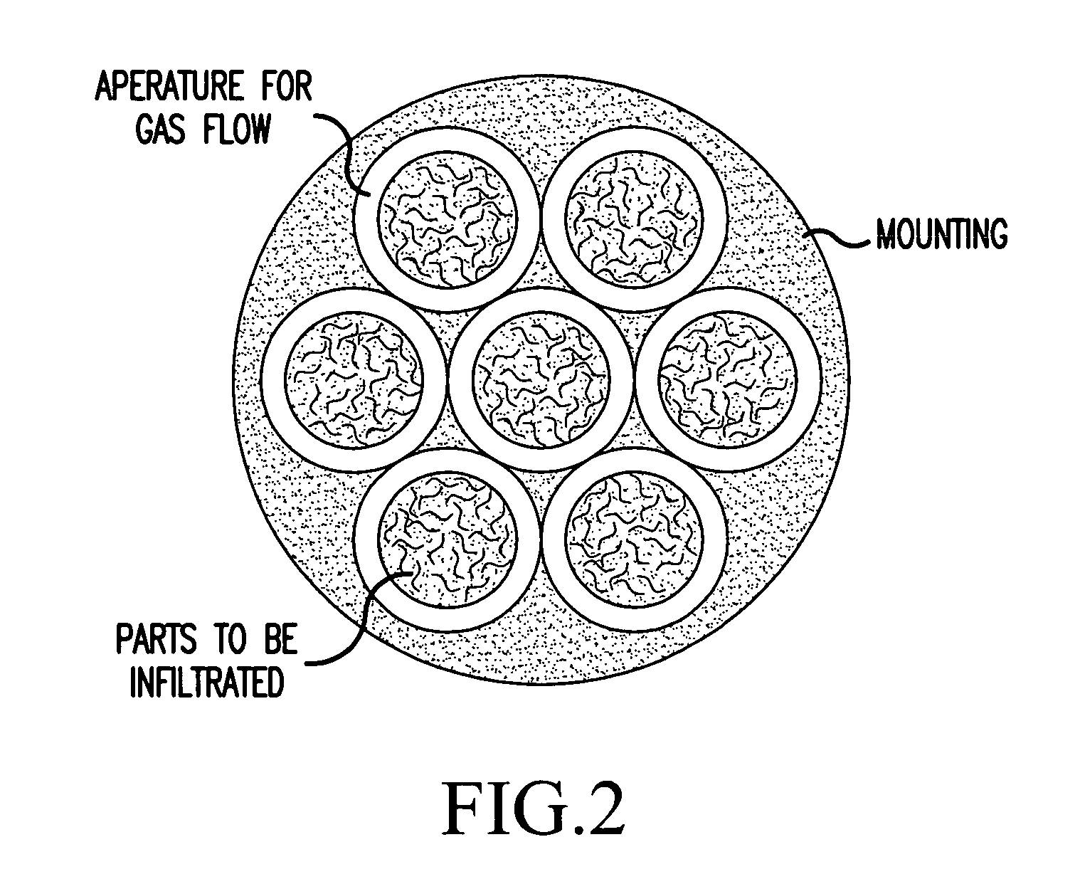
[0029]The method according to the invention may be conducted in a reactor having a specific reactor construction, or at least in a reactor with a special mounting. Reactors of the type shown in U.S. Pat. ...


PUM

PropertyMeasurementUnit
pressureaaaaaaaaaa
temperatureaaaaaaaaaa
widthaaaaaaaaaa

Abstract

Method of chemical vapor infiltration of a deposable carbon material into a porous carbon fiber preform in order to densify the carbon fiber preform. The method includes the steps of: situating the porous carbon fiber preform in the reaction zone; providing a linear flow of a reactant gas comprising deposable carbon material in the reaction zone at an initial reaction pressure of at most 50 torr to produce deposition of the deposable carbon material into the preform; and adjusting the pressure of the gas to reaction pressures lower than said initial reaction pressure while deposable carbon material continues to be deposited into the porous carbon fiber preform. This method enables attainment of a target increased density in a carbon fiber preform much more quickly than known processes. A programmed pressure swing throughout the CVI / CVD run may be set in order to provide a linear increase in density. Alternatively, step changes in pressure during the course of the densification process may be made to enhance the rate of densification. This method reduces the number of cycles and the required intermediate machining steps necessary to densify preforms.

Description

[0001]The invention concerns methods of chemical gas phase infiltration in the manufacture of carbon-carbon composite preforms intended for use in applications such as aircraft landing systems.BACKGROUND OF THE INVENTION[0002]Deposition of solid phases on substrates by decomposition of volatile or gaseous compounds which contain the solid phase elements is generally referred to as chemical vapor deposition. If this deposition takes place in the open pores of a porous substrate or in the cavities of a porous structure, then it is often referred to as chemical vapor infiltration. Chemical vapor deposition (CVD) and chemical vapor infiltration (CVI) allow a densification of structure or, when the porous structure consists of fibers, an introduction of a matrix and, with this, the production of composite, strengthened fiber materials. Both chemical vapor deposition as well as chemical vapor infiltration are extremely complex processes.[0003]In chemical gas phase infiltration, the volati...

Claims


Application Information

Patent Timeline
Patent Type & Authority Applications(United States)
IPC IPC(8): C23C16/26
CPCC23C16/045C04B35/83C23C16/26C23C16/45504C23C16/45557
Inventor WAGHRAY, AKSHAYWALKER, TERENCE B.
Owner HONEYWELL INT INC
Why Eureka
Try Eureka