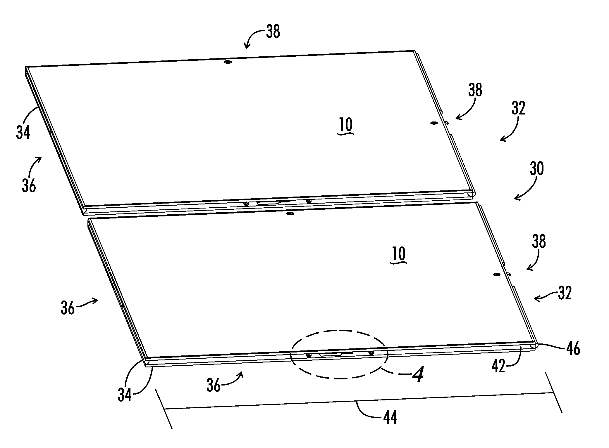
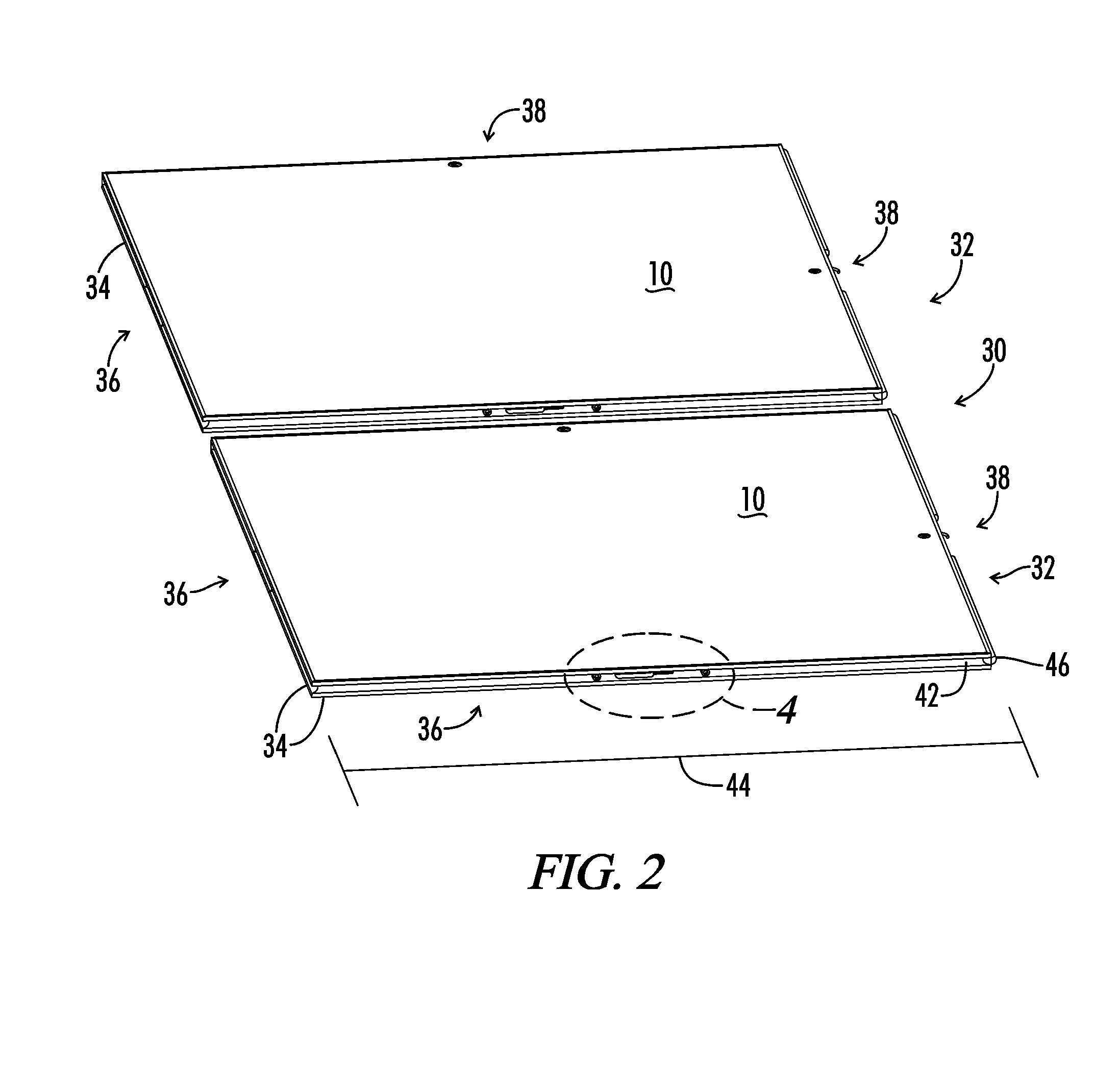
[0015]Also included is a method of preventing lateral panel movement when a floor is assembled. The panels are secured together by the
cam locks which are located in the male
extrusion lengths. The method used to prevent the panels from sliding laterally is accomplished with apertures located on the male side in the section cutout for the lock to receive two protruding pieces, such as cap head screws, located on the female side.
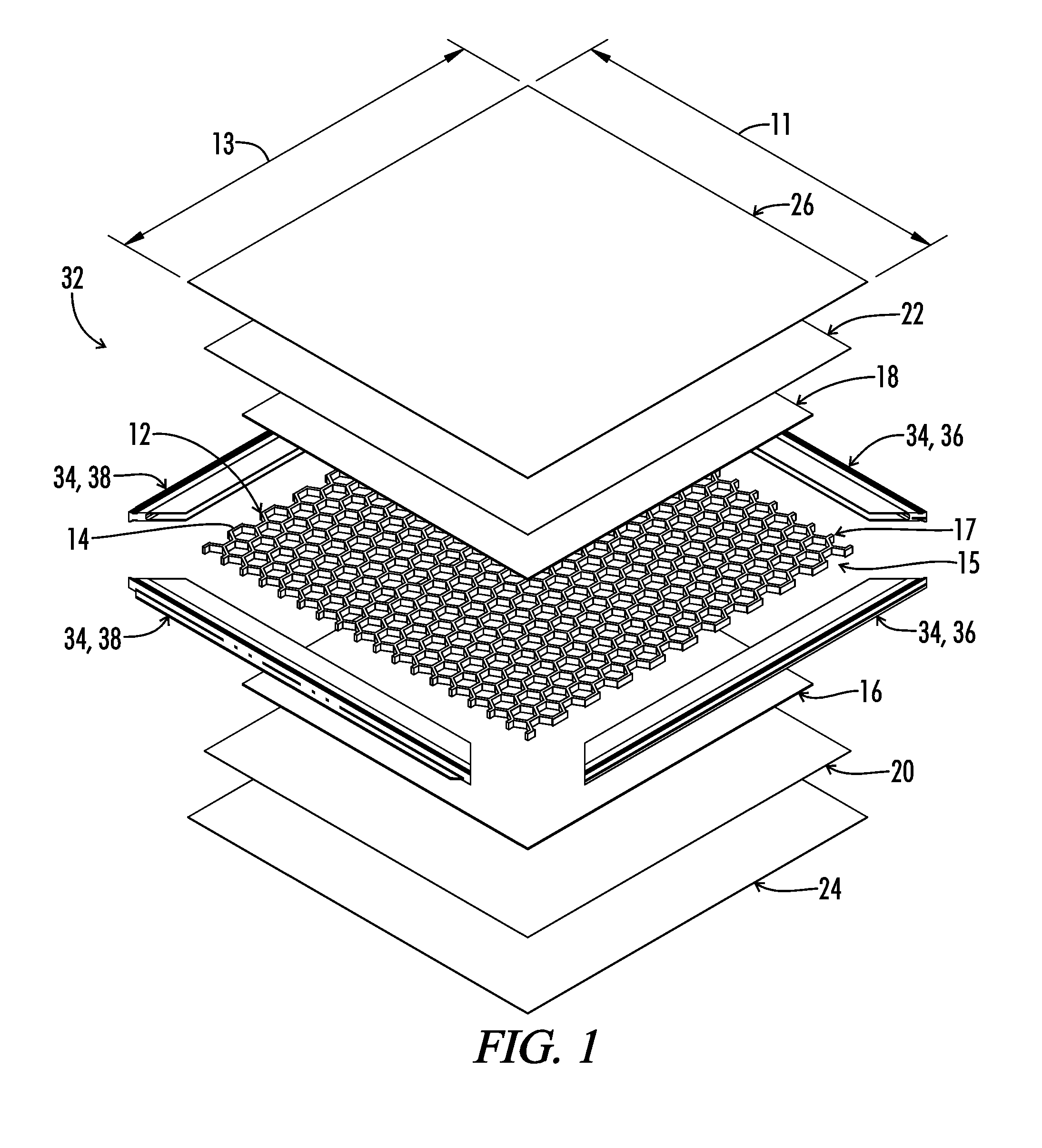
[0017]Advantages of the panels of the current invention, as compared to those of the prior art, include a waterproof characteristic and a lighter weight panel that facilitates transportation and
assembly. The current invention can have a reversibility option with multiple patterns, designs and / or color options on the opposing sides. The various
layers and
skin have superior adhesion due to the impregnation and attachment of the skins during the curing process and the superior
adhesive characteristics of polyurethane. The inventive panels have a substantial labor saving cost and specifically do not require a mold for their construction. This is an
advantage since the use of a mold can severely
restrict the economics of producing large panels and requires significant
capital investment for the molds and presses. A mold also requires cleaning and maintenance both of which add to cost and time for the production of the panels. As such, the
elimination of the use of a mold in panel construction can greatly reduce the production time and increase
cost savings during the production of the inventive panels.
[0018]For example, the molds discussed in some of the prior art, namely U.S. Pat. No. 6,761,953 use an open mold containing the outer layer and optionally the decorative layer. The prior art fails to place the
layers on to the composite materials outside of a press and without a mold. The production of the current inventive panels is facilitated by the flat geometry of the parts and the use of a pre formed perimeter
enclosure, such as aluminum or
elastomer edging. The
elastomer edge can provide part shape opportunities that are not possible with
extrusion.
[0019]Additionally, the inventive panels can be approximately 30% thinner than the existing panels which can enhance the safe use and operation of the panel. For example a thinner panel reduces the likelihood of trips and falls caused by the thickness of the panels when laid flat and used in a portable flooring embodiment. Additionally, the exterior surfaces on the inventive panels are superior in terms of wear, durability, and maintenance thereof. Additionally the panel
lateral movement suppression
system is a unique, cost effective, and practical method to prevent the panels from sliding when engaged.
[0020]The inventive panels can have various applications in numerous industries. These industries include hospitality and entertainment industries such as: hotel,
recreation centers, banquet halls, conference centers, stadiums, schools, outdoor activities with and without tents, and other similar facilities / locations. For example, portable flooring made in accordance with the current inventive panels can be set up and used indoors or outdoors with minimal
assembly and disassembly time. These inventive panels facilitate these applications due to their strength, durability, waterproof nature, light weight, and positive
interconnection between adjacent panels. For example, dance floors, tent floors, stage floors or other portable flooring applications can be ideally made using the inventive panels. Flooring so made can include a perimeter composed of an
elastomer or extruded
metal framework using
tongue and groove profiles for panel
interconnection. Alternately at least one of the sides can be shaped to interact with supporting feet and / or legs used to facilitate the upright placement of the panels, such as in a wall configuration.
[0023]Still another object of the present invention is to provide an improved panel that can be used in the making of a portable floor, folding tables, risers, event staging, and wall partitions.

