Supercharging control for an internal combustion engine

a technology of internal combustion engine and supercharging control, which is applied in the direction of electric control, liquid fuel engine, mechanical equipment, etc., can solve the problems of insufficient energy for the turbine of the exhaust gas turbocharger the range of variation of air/fuel ratio is very restricted, and the turbine of the exhaust gas turbocharger does not receive enough energy to deliver the maximum charge pressure. , to achieve the effect of improving the load capacity of the engine and reducing the loss of efficiency steady

Inactive Publication Date: 2008-06-05
ABB TURBO SYST
View PDF10 Cites 13 Cited by
  • Summary
  • Abstract
  • Description
  • Claims
  • Application Information

AI Technical Summary

Benefits of technology

[0010]The object on which the disclosure is based is that of creating a control for an internal combustion engine which

Problems solved by technology

While the control of air and fuel quantities can take place independently in a wide range in the case of diesel engines, in spark-ignition engines, the range of variation of the air/fuel ratio is very restricted.
The known problem of turbo lag however occurs when the engine power is so low that, despite the closed overpressure valve (wastegate), the turbine of the exhaust gas turbocharger does not receive enough energy to deliver the maximum charge pressure.
The above-described types of

Method used


Image

  • Supercharging control for an internal combustion engine
  • Supercharging control for an internal combustion engine
  • Supercharging control for an internal combustion engine

Examples


Embodiment Construction

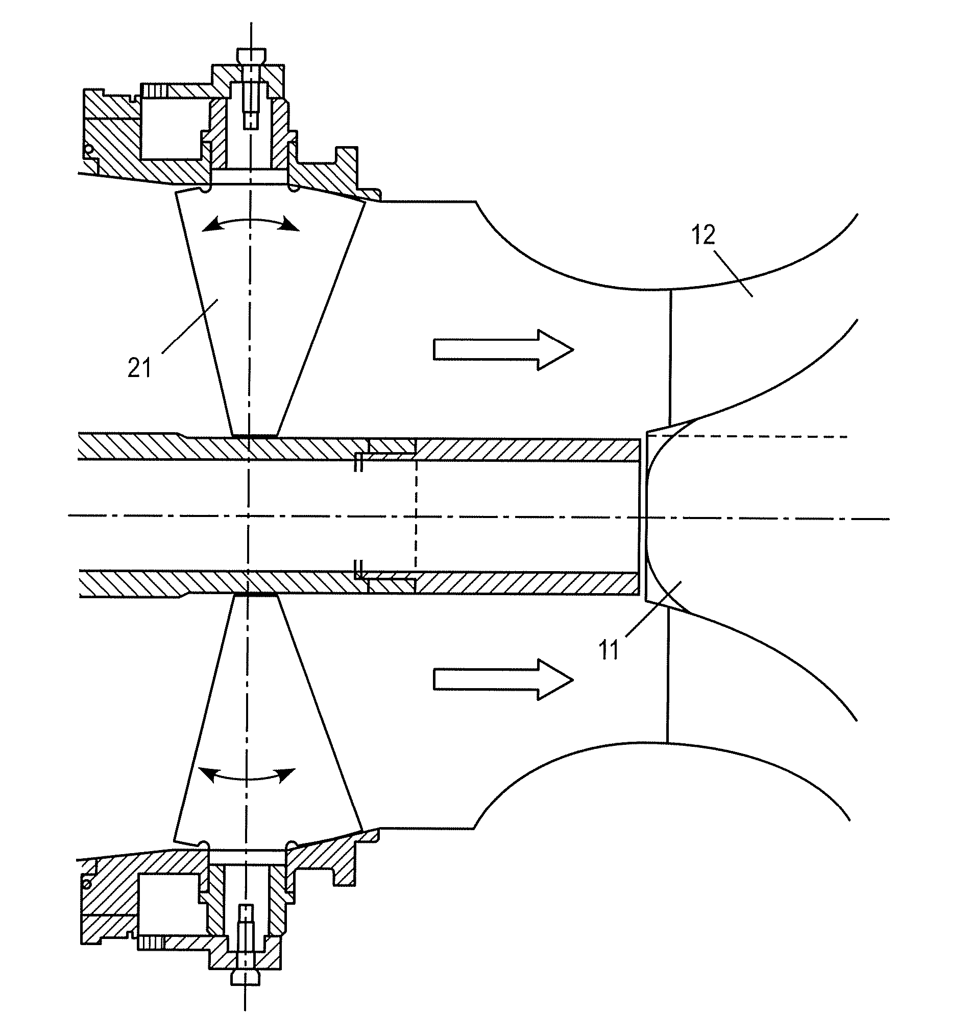
[0023]FIG. 1 shows a section through the compressor inlet of an exhaust gas turbocharger. The compressor wheel is indicated in a rudimentary fashion at the right-hand side. Said compressor wheel comprises a hub 11 and moving blades 12 which are fastened to the hub. Arranged in the intake region of the compressor is a pre-swirl device which comprises a plurality of guide blades 21. The guide blades are, in the illustrated embodiment, arranged radially with respect to the turbocharger shaft and can in each case rotate about an axis. A more or less intense deflection of the air flow is brought about depending on the alignment of the guide blades, so that said air flow is acted on with more or less swirl. The swirl can, if it is in the same rotational direction as the compressor wheel, lead to a reduction in the compressor drive power, and consequently, at constant turbine power, to an increase in the rotor rotational speed.

[0024]In steady-state operation of a throttled internal combust...


PUM


Abstract

By means of a pre-swirl device, in steady-state engine operation, the rotational speed lines of the compressor are moved, by increasing the swirl at the compressor inlet in the rotational direction of the compressor, to such an extent that the steady-state operating point of the compressor comes to rest approximately at the absorption limit of the compressor. In this way, the level of the charge pressure can be adjusted in a controlled fashion to the value required for the respective engine operating point. In the event of a sudden increase in the engine load, it is possible by resetting the pre-swirl grate to generate a charge pressure increase without a time-consuming rotor acceleration. The pre-swirl device therefore simultaneously assumes the functions of charge pressure and engine load control.

Description

RELATED APPLICATIONS[0001]This application claims priority under 35 U.S.C. §119 to EP Application 05405335.0 filed in European Patent Office on 4 May 2005, and as a continuation application under 35 U.S.C. §120 to PCT / CH2006 / 000229 filed as an International Application on 26 Apr. 2006 designating the U.S., the entire contents of which are hereby incorporated by reference in their entireties.TECHNICAL FIELD[0002]The disclosure relates to the field of supercharged internal combustion engines. A control system for the charging of an internal combustion engine and a method for operating a supercharged internal combustion engine are disclosed.BACKGROUND INFORMATION[0003]Supercharged internal combustion engines (e.g. gas-, gasoline- or diesel-fueled) which operate in a wide rotational speed and load range generally require at least two control systems: a main control which controls the engine power via the fuel supply, and an auxiliary control which can generate the required charging pres...

Claims


Application Information

Patent Timeline
IPC IPC(8): F02D23/00
CPCF02B37/225F02D41/0007Y02T10/144F04D27/0246F04D29/4213F02D2009/0283Y02T10/12F02B37/22F02D23/00F02D41/00F02B37/24
Inventor CODAN, ENNIOBERNARD, OLIVIER
Owner ABB TURBO SYST
Why Eureka
Try Eureka