Electrolytic apparatus for molten salt

Inactive Publication Date: 2008-06-05
TOYO TANSO KK
View PDF9 Cites 17 Cited by
  • Summary
  • Abstract
  • Description
  • Claims
  • Application Information

AI Technical Summary

Benefits of technology

[0022]According to the present invention, as the effect of insulation is improved by forming the heat insulating zone, it is possible to make the apparatus more compact than conventional electrolytic apparatuses. Accordingly, the heat discharge to the outside can be dropped, and the electrolytic cell is heated effectively, as the result, the waste of energy can be minimized by heat exchanging means. Also, as the heat insulating zone is decom

Problems solved by technology

When the pressure of heat insulating zone is less than 10 kPa, the thermal conductivity by gases cannot be lowered, which decreases the efficiency

Method used


Image

  • Electrolytic apparatus for molten salt
  • Electrolytic apparatus for molten salt
  • Electrolytic apparatus for molten salt

Examples


Embodiment Construction

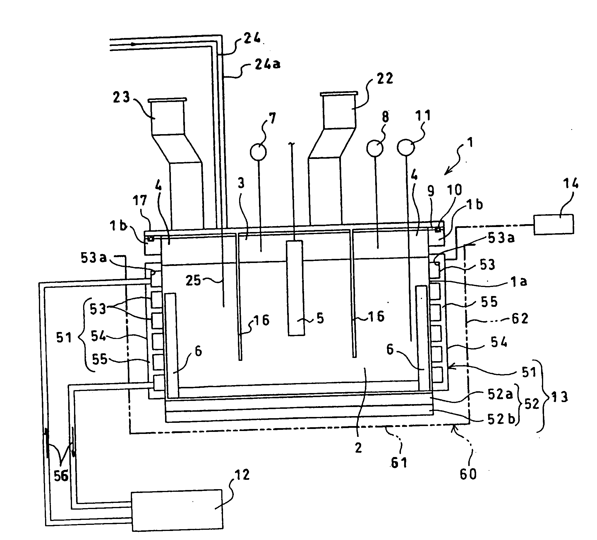
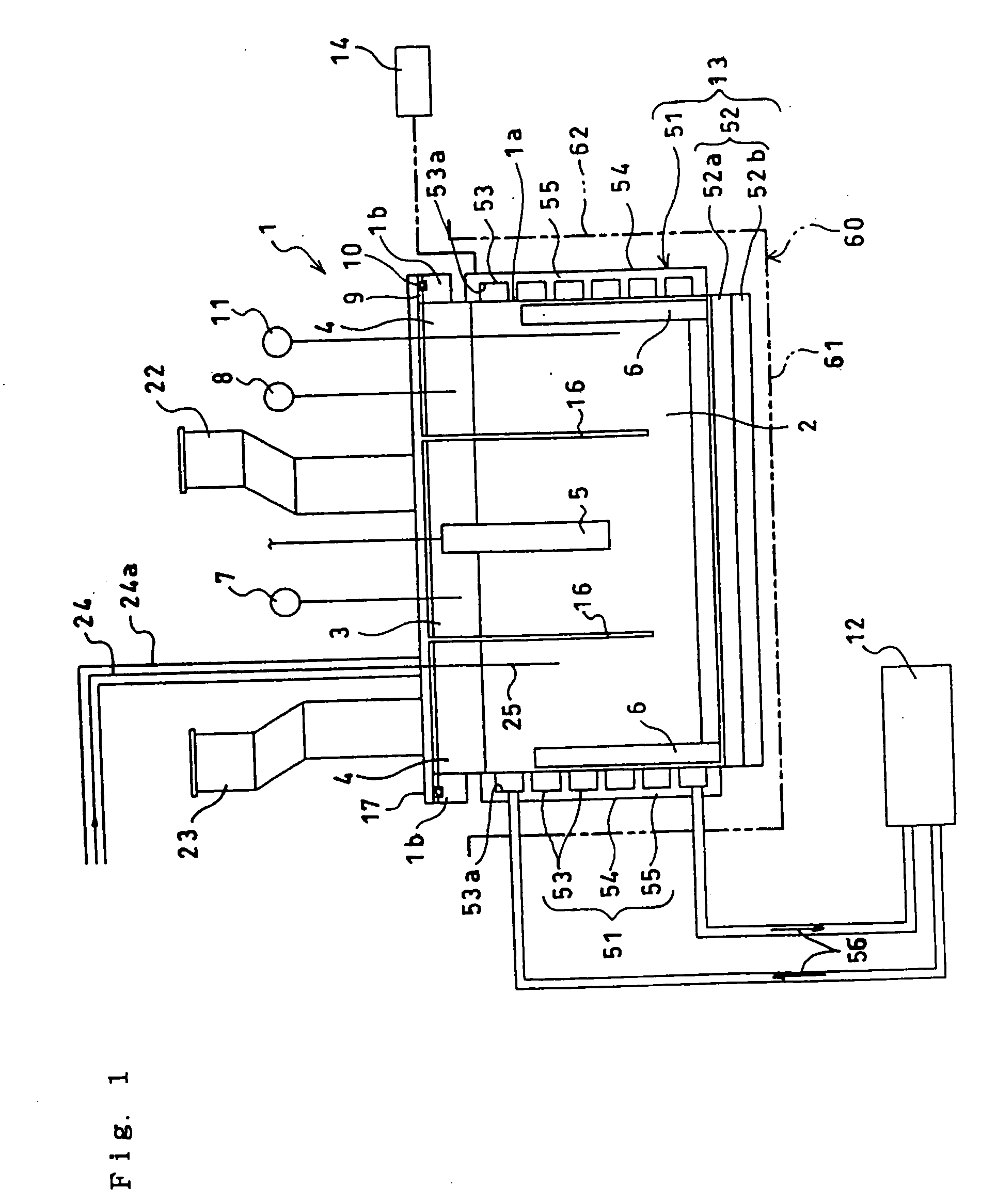
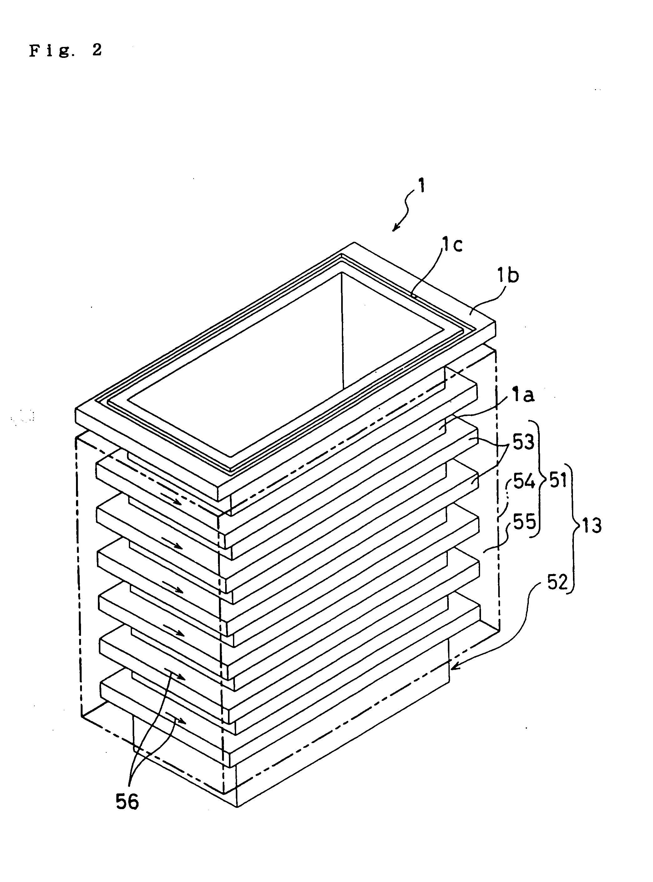
[0029]Hereinafter, based on the drawings 1-5, preferred embodiments of the present invention relating to the fluorine gas generator are described more in detail.

[0030]The construction of fluorine gas generator (an electrolytic apparatus for molten salt) is shown in FIG. 1. 1 is an electrolytic cell consisting of electrolytic cell body 1a and upper lid 17, and 2 is an electrolytic bath consisting of mixed molten salt made of KF-2HF type, 3 is an anode chamber, 4 is a cathode chamber, 5 is an anode, 6 is a cathode. 22 is an outlet port for C-1 generated fluorine gas in anode chamber 3. 11 is a thermometer to measure the temperature in the electrolytic bath 2, 13 is a heat exchanging means of electrolytic cell 1, 12 is an apparatus for warm water heating to supply the warm water for heat exchanging means 13. 51 is a warm water jacket disposed on the side of electrolytic cell 1, which constructs heat exchanging means, 52 is a heating parts (secondary heat exchanging means), which constr...


PUM

PropertyMeasurementUnit
Electric propertiesaaaaaaaaaa
Heataaaaaaaaaa

Abstract

An electrolytic apparatus for molten salt disposed on an electrolytic cell to electrolyze an electrolytic bath consisting of the mixed molten salt. The apparatus including a first heat exchanging means to heat and/or cool an electrolytic cell body. The apparatus including a support member comprising one of a flange part and an upper lid. The apparatus including a cover member. The apparatus including an electric insulating material and a gas sealing material disposed between the support member and the cover member for simultaneous electric insulation and gas sealing.

Description

CROSS REFERENCE TO RELATED APPLICATIONS[0001]This application is based upon and claims the benefit of priority under 35 U.S.C. §120 from U.S. patent application Ser. No. 10 / 760,505, filed on Jan. 21, 2004, which claims the benefit of priority under 35 U.S.C. §119 (a)-(d) from prior Japanese Patent Application 2003-013778, filed on Jan. 22, 2003; the entire contents of each of which are incorporated herein by reference.BACKGROUND OF THE INVENTION[0002]1. Field of the Invention[0003]The present invention relates to an electrolytic apparatus for molten salt, more particularly to an electrolytic apparatus for molten salt, which can be compact, with excellent sealing property.[0004]2. Description of the Related Art[0005]Fluorine gas is an indispensable basic gas in the semiconductor manufacturing field. Further, fluorine gas is used for the semiconductor manufacturing field independently, but nitrogen trifluoride gas (hereinafter referred to as NF3 gas) is synthesized based on fluorine g...

Claims


Application Information

Patent Timeline
IPC IPC(8): C25B9/00C25B9/17
CPCC25B1/245C25B15/02C25B9/06C25B9/17C25B15/021C01B7/20
Inventor HIRAIWA, JIROYOSHIMOTO, OSAMUTOJO, TETSURO
Owner TOYO TANSO KK
Why Eureka
Try Eureka