Method for removing carbon dioxide in high-purity gas
A high-purity gas and carbon dioxide technology, applied in chemical instruments and methods, separation methods, gas treatment, etc., can solve the problem of high energy consumption and achieve the effect of no secondary pollution, good application prospects, and high-efficiency deep removal
- Summary
- Abstract
- Description
- Claims
- Application Information
AI Technical Summary
Problems solved by technology
Method used
Image
Examples
Embodiment 1
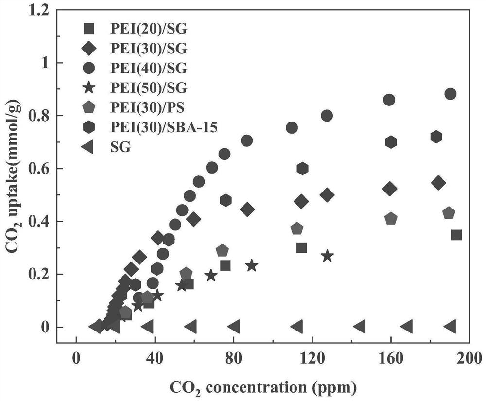
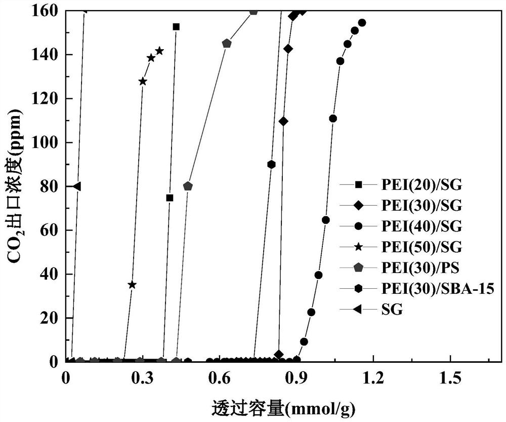
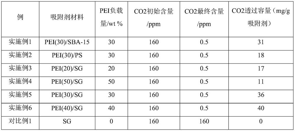
[0050] A high-efficiency deep adsorption removal of CO 2 The preparation method of the PEI-loaded adsorbent, the preparation of the PEI-loaded adsorbent comprises the following steps:
[0051] (1) 1g PEI was dissolved in 20mL methanol, stirred for 60min to obtain PEI / methanol solution;
[0052] (2) adding the pre-vacuum-dried SBA-15 to the PEI / methanol solution of step (1) according to the required amount, and continue to stir to form a slurry mixture, and stir at room temperature for 5h;
[0053] (3) The material obtained in step 2 is continuously purged under a nitrogen flow (50 mL / min) atmosphere at 45° C. until the sample forms a dry powder to obtain a PEI-loaded adsorbent, wherein the mass ratio of PEI in the PEI-loaded adsorbent is is 30%, then the PEI-loaded adsorbent is sealed for preservation or the test material is adsorbed to remove CO 2 performance.
Embodiment 2
[0055] A high-efficiency deep adsorption removal of CO 2 The preparation method of the PEI-loaded adsorbent, the preparation of the adsorbent material comprises the following steps:
[0056] (1) 1g PEI was dissolved in 20mL methanol, stirred for 60min to obtain PEI / methanol solution;
[0057] (2) adding the pre-vacuum-dried PS powder to the PEI / methanol solution of step (1) according to the required amount, and continue to stir to form a slurry mixture, and stir at room temperature for 5h;
[0058] (3) The material obtained in step 2 is continuously purged under a nitrogen flow (50 mL / min) atmosphere at 45° C. until the sample forms a dry powder to obtain a PEI-loaded adsorbent, wherein the mass ratio of PEI in the PEI-loaded adsorbent is is 30%, then the PEI-loaded adsorbent is sealed for preservation or the test material is adsorbed to remove CO 2 performance.
Embodiment 3
[0060] A high-efficiency deep adsorption removal of CO 2 The preparation method of the PEI-loaded adsorbent, the preparation of the adsorbent material comprises the following steps:
[0061] (1) 1g PEI was dissolved in 20mL methanol, stirred for 60min to obtain PEI / methanol solution;
[0062] (2) adding the preliminarily 108 ℃ vacuum-dried silica gel (SG) to the PEI / methanol solution in step (1) according to the required amount, and continue to stir to form a slurry mixture, and stir at room temperature for 5h;
[0063] (3) The material obtained in step 2 is continuously purged under a nitrogen flow (50 mL / min) atmosphere at 45° C. until the sample forms a dry powder to obtain a PEI-loaded adsorbent, wherein the mass ratio of PEI in the PEI-loaded adsorbent is is 20%, then the PEI-loaded adsorbent is sealed for preservation or the test material is adsorbed to remove CO 2 performance.
PUM
| Property | Measurement | Unit |
|---|---|---|
| pore size | aaaaa | aaaaa |
| specific surface area | aaaaa | aaaaa |
| pore size | aaaaa | aaaaa |
Abstract
Description
Claims
Application Information
 - R&D
- Intellectual Property
- Life Sciences
- Materials
- Tech Scout
- Unparalleled Data Quality
- Higher Quality Content
- 60% Fewer Hallucinations
Browse by: Latest US Patents, China's latest patents, Technical Efficacy Thesaurus, Application Domain, Technology Topic, Popular Technical Reports.
© 2025 PatSnap. All rights reserved.Legal|Privacy policy|Modern Slavery Act Transparency Statement|Sitemap|About US| Contact US: help@patsnap.com


