Beam tilting patch antenna using higher order resonance mode

a patch antenna and higher-order technology, applied in the field of patch antennas, can solve the problems of patch antennas not being typically disposed on the windows of vehicles, obtuse-looking devices, and bulky sdars-compliant antennas,

Active Publication Date: 2008-06-05
AGC AUTOMOTIVE AMERICAS CO A DIV OF AGC FLAT GLASS NORTH AMERICA INC
View PDF58 Cites 18 Cited by
  • Summary
  • Abstract
  • Description
  • Claims
  • Application Information

AI Technical Summary

Benefits of technology

[0015]The at least one parasitic structure also acts to tilt the radiation beam away from an axis perpendicular to the radiating element.

Problems solved by technology

SDARS compliant antennas are frequently bulky, obtuse-looking devices mounted on a roof of a vehicle.
When the radiating element is disposed on a window of the vehicle, this large “footprint” often obstructs the view of the driver.
Therefore, these patch antennas are not typically disposed on the windows of the vehicle.
However, even when these patch antennas are disposed on the windows of the vehicle, certain parts of the vehicle, such as a roof, may block RF signals and prevent the RF signals from reaching the antenna at certain elevation angles.
Even if the roof does not block the RF signals, the roof may mitigate the RF signals, which may cause the RF signal to degrade to an unacceptable quality.
When this happens, the antenna is unable to receive the RF signals at those elevation angles a

Method used


Image

  • Beam tilting patch antenna using higher order resonance mode
  • Beam tilting patch antenna using higher order resonance mode
  • Beam tilting patch antenna using higher order resonance mode

Examples


first embodiment

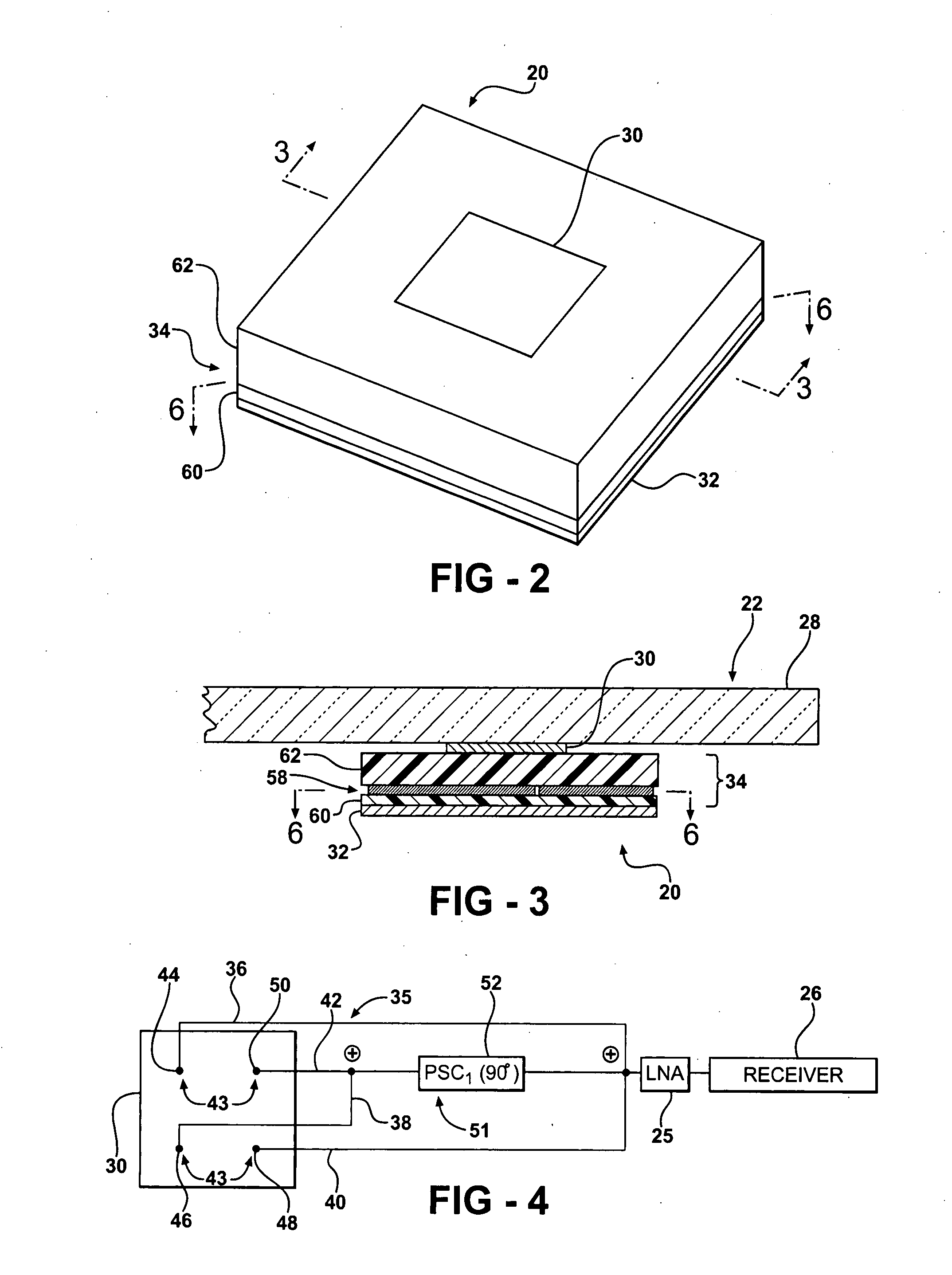
[0035]Referring to FIG. 2, showing the invention, the antenna 20 includes a radiating element 30 formed of an electrically conductive material as described below. The radiating element 30 is also commonly referred to by those skilled in the art as a “patch” or a “patch element”. The radiating element 30 preferably defines a generally rectangular shape, specifically a square shape. Each side of the radiating element 30 measures about ¼ of an effective wavelength λ of the RF signal to be received by the antenna 20. RF signals transmitted by SDARS providers typically have a frequency from 2.32 GHz to 2.345 GHz. Specifically, XM Radio broadcasts at a center frequency of 2.338 GHz. Therefore, each side of the radiating element 30 measures about 24 mm. However, those skilled in the art realize alternative embodiments where the radiating element 30 defines alternative shapes and sizes based on the desired frequency and other considerations.

[0036]The antenna 20 also includes a ground plane ...

second embodiment

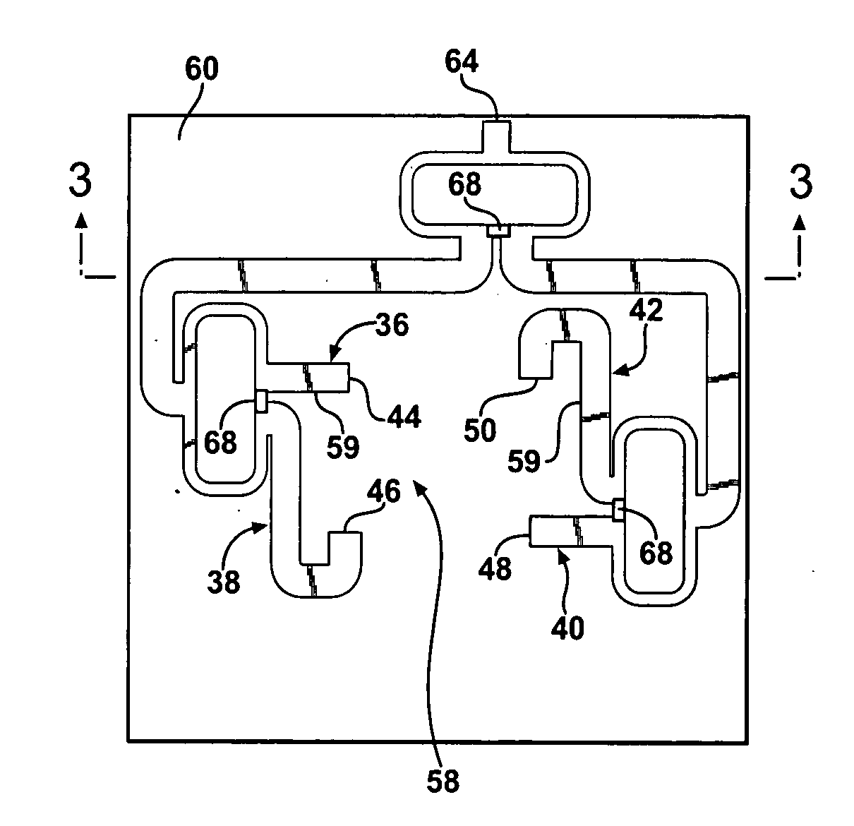
[0048]FIGS. 7 and 8 show the second embodiment where there is a direct connection between the feed lines 36, 38, 40, 42 and the radiating element 30. In this embodiment, the ground plane 32 is sandwiched between the first and second dielectric layers 60, 62. The feed line network 58 is disposed on the first dielectric layer 60 on the opposite side from the ground plane 32. A plurality of pins 64 electrically connect the feed lines to the radiating element 30. Passage holes (not numbered) are defined in the ground plane 32 to prevent an electrical connection between the feed lines 36, 38, 40, 42 and the ground plane 32.

[0049]In both the first and second embodiments, the feed line network 58 is also utilized to shift the phase of a signal applied to the feed lines 36, 38, 40, 42, thus, acting as the phase shift circuits 51 described above. This phase shifting is accomplished due to the inductive and capacitive properties of the conductive strips 59 of the feed line network 58. The ind...

third embodiment

[0052]The antenna 20 may also include at least one parasitic structure 66 for further directing and / or tilting the radiation beam. Referring now to FIG. 9, which shows the invention, the parasitic structure 66 is disposed adjacent to the radiating element 30 and separated from the radiating element 30. Said another way, the parasitic structure 66 is not in direct contact with the radiating element 30. However, the proximity of the parasitic structure 66 with the radiating element 30 affects the radiating beam. Preferably, the parasitic structure 66 is disposed substantially co-planar with the radiating element 30. It is also preferred that each of the parasitic structures 66 includes a plurality of strips 67 formed of an electrically conductive material. However, those skilled in the art realize other techniques for forming the parasitic structures 66, other than the preferred plurality of strips 67.

[0053]As stated above, the radiating element 30 defines a generally rectangular shap...


PUM


Abstract

A patch antenna receives circularly polarized RF signals from a satellite. The antenna includes a radiating element. A plurality of feed lines feed the radiating element at a plurality of feed points. The feed points are spaced apart to generate a circularly polarized radiation beam solely in a higher order mode at a desired frequency. The antenna may include a plurality of parasitic structures. The feed point spacing and/or the parasitic structures tilt the radiating beam away from an axis perpendicular to the radiating element. Thus, the patch antenna provides excellent RF signal reception from satellites at low elevation angles.

Description

CROSS REFERENCE TO RELATED APPLICATION[0001]This application claims the benefit of U.S. Provisional Application No. 60 / 868,436, filed Dec. 4, 2006.BACKGROUND OF THE INVENTION[0002]1. Field of the Invention[0003]The subject invention relates generally to a patch antenna. Specifically, the subject invention relates to a patch antenna for receiving circularly-polarized radio frequency signals from a satellite.[0004]2. Description of the Related Art[0005]Satellite Digital Audio Radio Service (SDARS) providers use satellites to broadcast RF signals, particularly circularly polarized RF signals, back to receiving antennas on Earth. The elevation angle between a satellite and an antenna is variable depending on the location of the satellite and the location of the antenna. Within the continental United States, this elevation angle may be as low as 20° from the horizon. Accordingly, specifications of the SDARS providers require a relatively high gain at elevation angles as low as 20° from t...

Claims


Application Information

Patent Timeline
IPC IPC(8): H01Q1/38H01Q1/50
CPCH01Q1/1271H01Q9/0435H01Q9/0407
Inventor SURITTIKUL, NUTTAWITLEE, KWAN-HOVILLARROEL, WLADIMIRO
Owner AGC AUTOMOTIVE AMERICAS CO A DIV OF AGC FLAT GLASS NORTH AMERICA INC
Why Eureka
Try Eureka