
SYSTEMS AND METHODS IMPLEMENTING FREQUENCY-STEERED ACOUSTIC ARRAYS FOR 2D and 3D IMAGING

a frequency-steered acoustic array and imaging system technology, applied in the direction of ultrasonic/sonic/infrasonic wave beacon systems, direction finders, instruments, etc., can solve the problems of high frame rate, high frame rate, and low imaging scene stability, and achieve the effect of increasing image quality

Active Publication Date: 2008-06-05
TELEDYNE RESON
View PDF21 Cites 51 Cited by
  • Summary
  • Abstract
  • Description
  • Claims
  • Application Information

AI Technical Summary

Benefits of technology

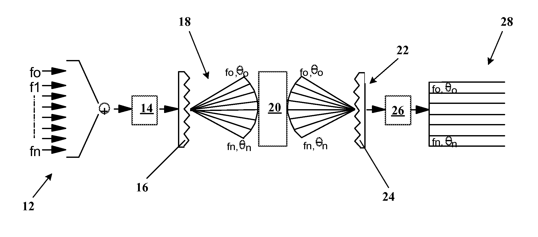
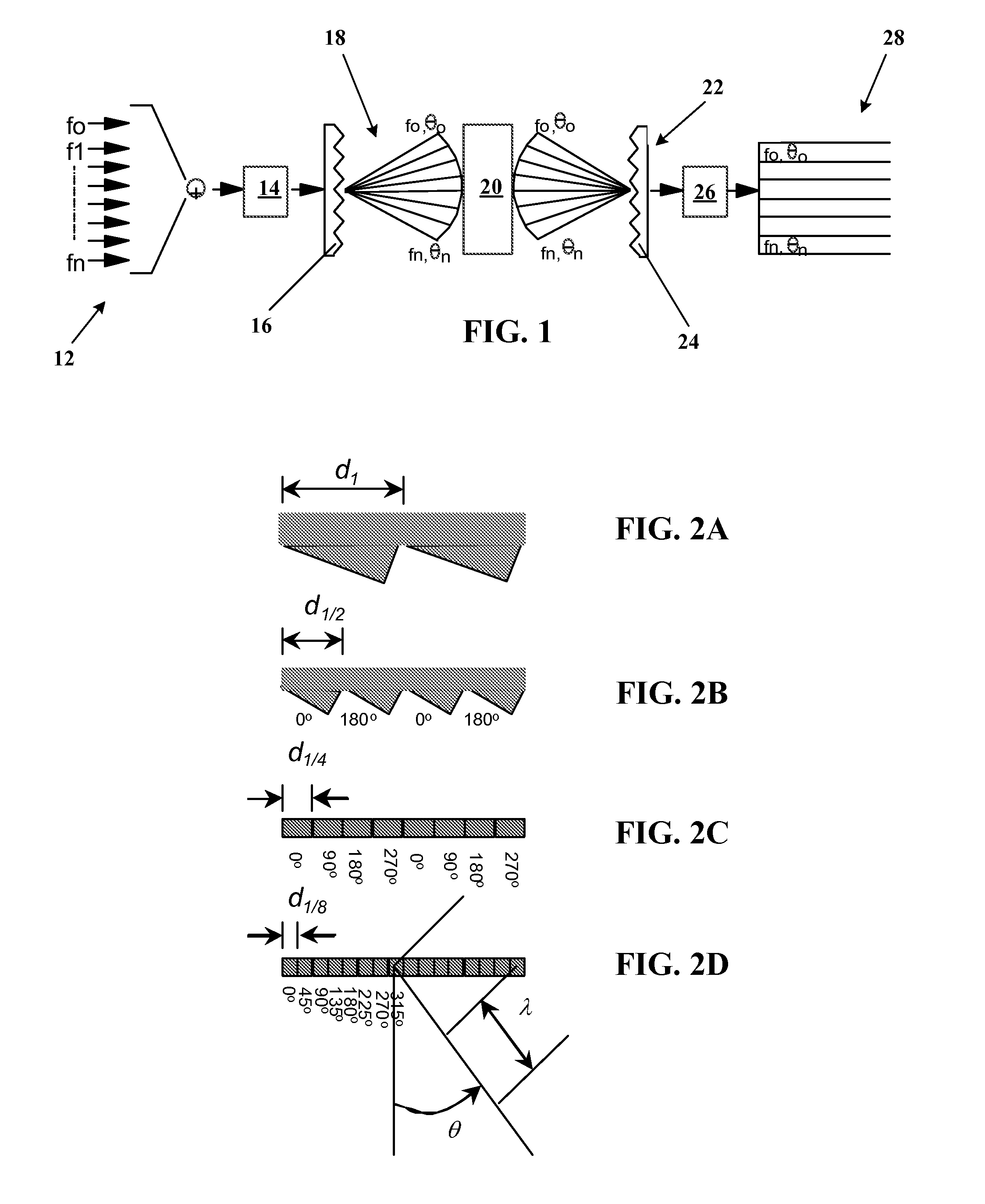
[0012]Methods and systems of the present invention employ frequency-steered acoustic arrays and time-frequency signal analysis to provide acoustic imaging systems that produce multiple, angularly dispersed beams steered with frequency. These frequency-steered systems may be implemented with data processing techniques to generate a 2D image using a single hardware channel because the frequency-steered array effectively multiplexes the beam signals into separate frequency channels. If the frequency-steered array technique is used in conjunction with conventional array design and beamforming techniques, a 3D acoustic imaging system may be implemented using the same number of hardware channels that would be required for a conventional 2D system. These systems operate at the same data rate because the bandwidth of the reduced number of hardware channels increases to carry the extra spatial information. A frequency-steered array imaging system can thus collect an entire image with a single transmission, providing high resolution images at high frame rates and requiring low imaging scene stability.
[0013]Using frequency-steered arrays to produce 2D and / or 3D images in a sonar system implementation provides a number of advantages. First, because the frequency-steered array generates multiple beams using a single broadband signal, the amount of analog electronics required to produce an image is significantly reduced compared to that of traditional imaging sonar. By reducing the electronics required, the imaging sonar is significantly smaller, less expensive, and requires less power than traditional imaging sonar. Another advantage to using frequency-steered arrays in imaging sonar is that they are able to produce high quality images even in shallow waters. Traditional small sonar devices transmit and receive using a narrow frequency band, often with a relatively broad beam. In shallow water, these broad beam signals tend to be reflected from many surfaces and create what is commonly referred to as multi-path interference. These multi-path signals return from multiple directions (from the same target) and result in cluttered, confusing sonar images. Because a frequency-steered imaging system can generate many narrow beams in both transmit and receive modes, the system is less susceptible to multi-path signals and performs much better than conventional sonar devices in shallow water environments.

Problems solved by technology

A frequency-steered array imaging system can thus collect an entire image with a single transmission, providing high resolution images at high frame rates and requiring low imaging scene stability.
In shallow water, these broad beam signals tend to be reflected from many surfaces and create what is commonly referred to as multi-path interference.
These multi-path signals return from multiple directions (from the same target) and result in cluttered, confusing sonar images.

Method used


Image

  • SYSTEMS AND METHODS IMPLEMENTING FREQUENCY-STEERED ACOUSTIC ARRAYS FOR 2D and 3D IMAGING
  • SYSTEMS AND METHODS IMPLEMENTING FREQUENCY-STEERED ACOUSTIC ARRAYS FOR 2D and 3D IMAGING
  • SYSTEMS AND METHODS IMPLEMENTING FREQUENCY-STEERED ACOUSTIC ARRAYS FOR 2D and 3D IMAGING

Examples


Embodiment Construction

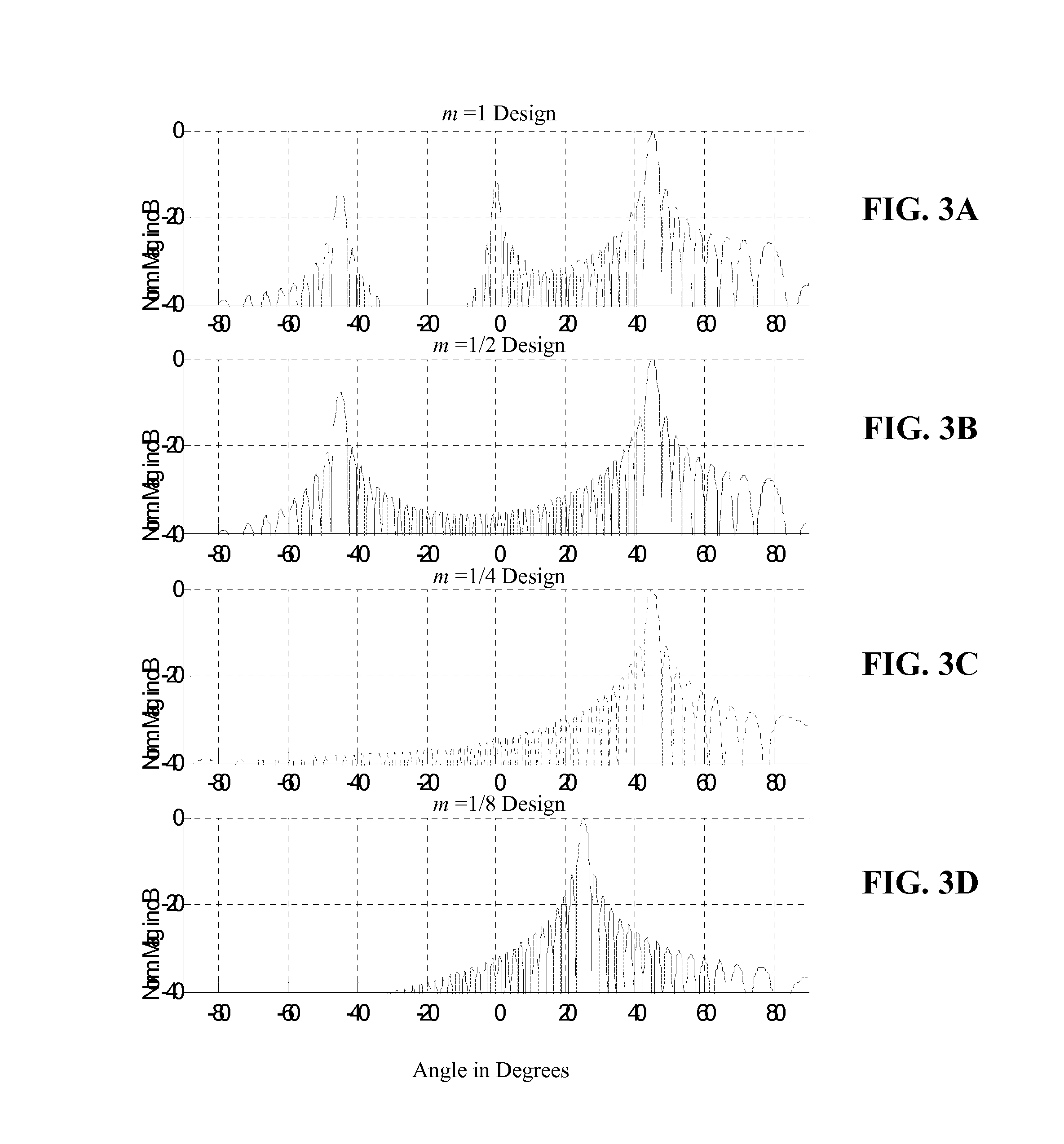
[0050]Frequency-steered acoustic array systems and methods of the present invention utilize a broadband acoustic pulse as an input signal to one or more frequency-steered arrays that may have periodic or aperiodic spacing or phasing of transducer elements that may be blazed and / or phase shifted, that may be provided in a single order or a multiple order configuration, and that may be operated in a transmit and / or receive mode. Multiple frequency-steered acoustic array systems may be arranged in an X- or T-configuration to provide desired fields of view, and selected array configurations may be used in linear and / or rotational mechanical scanning modes to produce a variety of 2D and 3D data sets that may be processed to produce 2D and 3D images.

[0051]The input pulse to a frequency-steered acoustic array operated in a transmit mode is preferably a broadband pulse such as an FM pulse, a scale-swept wavelet pulse train, a multi-wavelet or multi-frequency pulse, or another broadband puls...


PUM


Abstract

Frequency-steered acoustic arrays transmitting and / or receiving multiple, angularly dispersed acoustic beams are used to generate 2D and 3D images. Input pulses to the arrays are generally non-linear, frequency-modulated pulses. Frequency-steered acoustic arrays may be provided in one-dimensional linear and two dimensional planar and curvilinear configurations, may be operated as single order or multiple order arrays, may employ periodic or non-periodic transducer element spacing, and may be mechanically scanned to generate 2D and 3D volumetric data. Multiple imaging fields of view may generated in different directions by switching the polarity of phase-shifted array transducer elements. Multiple frequency-steered arrays arranged in an X-configuration provide a wide, contiguous field of view and multiple frequency steered arrays arranged in a T-configuration provide orthogonally oriented fields of view. Methods and systems for operating acoustic arrays in a frequency-steered mode in combination a mechanical beam steering mode, electronic time-delay and phase shift beam forming modes, and phase comparison angle estimation modes are also provided.

Description

REFERENCE TO PRIORITY APPLICATIONS[0001]This application is a continuation of U.S. patent application Ser. No. 10 / 889,406, filed Jul. 12, 2004, which claims priority to U.S. Provisional Application No. 60 / 485,981 filed Jul. 11, 2003 and U.S. Provisional Application No. 60 / 549,111 filed Mar. 1, 2004. The priority patent applications are incorporated herein by reference in their entireties.TECHNICAL FIELD OF THE INVENTION[0002]The present invention relates to methods and systems implementing frequency-steered acoustic arrays that are particularly useful for 2D and 3D sonar and ultrasound device imaging systems.BACKGROUND OF THE INVENTION[0003]Traditional methods for forming and steering beams produced by an array of acoustic transducers involve phased or time-delayed acoustic pulses and require that each stave of the array be sampled as a separate hardware channel. Although this approach may produce effective, high-resolution imaging systems, it also requires substantial support elect...

Claims


Application Information

Patent Timeline
Patent Type & Authority Applications(United States)
IPC IPC(8): G01S1/76G01S15/89G10K11/34
CPCG01S15/89G01S15/8952G10K11/34G10K11/343G01S15/8993G01S7/6245
Inventor BACHELOR, SCOTT T.THOMPSON, ROGER LEESEAWALL, JASON L.
Owner TELEDYNE RESON
Learn More