Photoelectrochemical system for hydrogen production from water

a photoelectrochemical and water-based technology, applied in electrochemical generators, instruments, energy input, etc., can solve the problems of corrosiveness of optical electrodes, limitation of electrode material selection, poor corrosion resistance of silicon photoelectric cells widely used in the art,

Inactive Publication Date: 2008-06-05
KOREA INST OF SCI & TECH
View PDF8 Cites 29 Cited by
  • Summary
  • Abstract
  • Description
  • Claims
  • Application Information

AI Technical Summary

Benefits of technology

[0006]It is, therefore, an object of the present invention to provide a PEC system which can solve the above-mentioned problems.

Problems solved by technology

However, the above PEC systems have the disadvantages of the corrosiveness of optical electrodes and the limitation imposed on the selection of electrode material which comes directly in contact with the electrolyte solution.
In particular, the silicon photoelectric cell widely used in the art has poor corrosion resistance toward aqueous electrolyte solutions.

Method used


Image

  • Photoelectrochemical system for hydrogen production from water
  • Photoelectrochemical system for hydrogen production from water
  • Photoelectrochemical system for hydrogen production from water

Examples


example 1

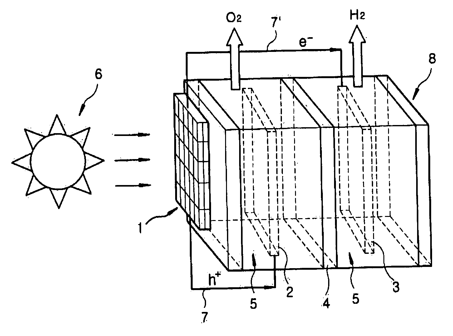
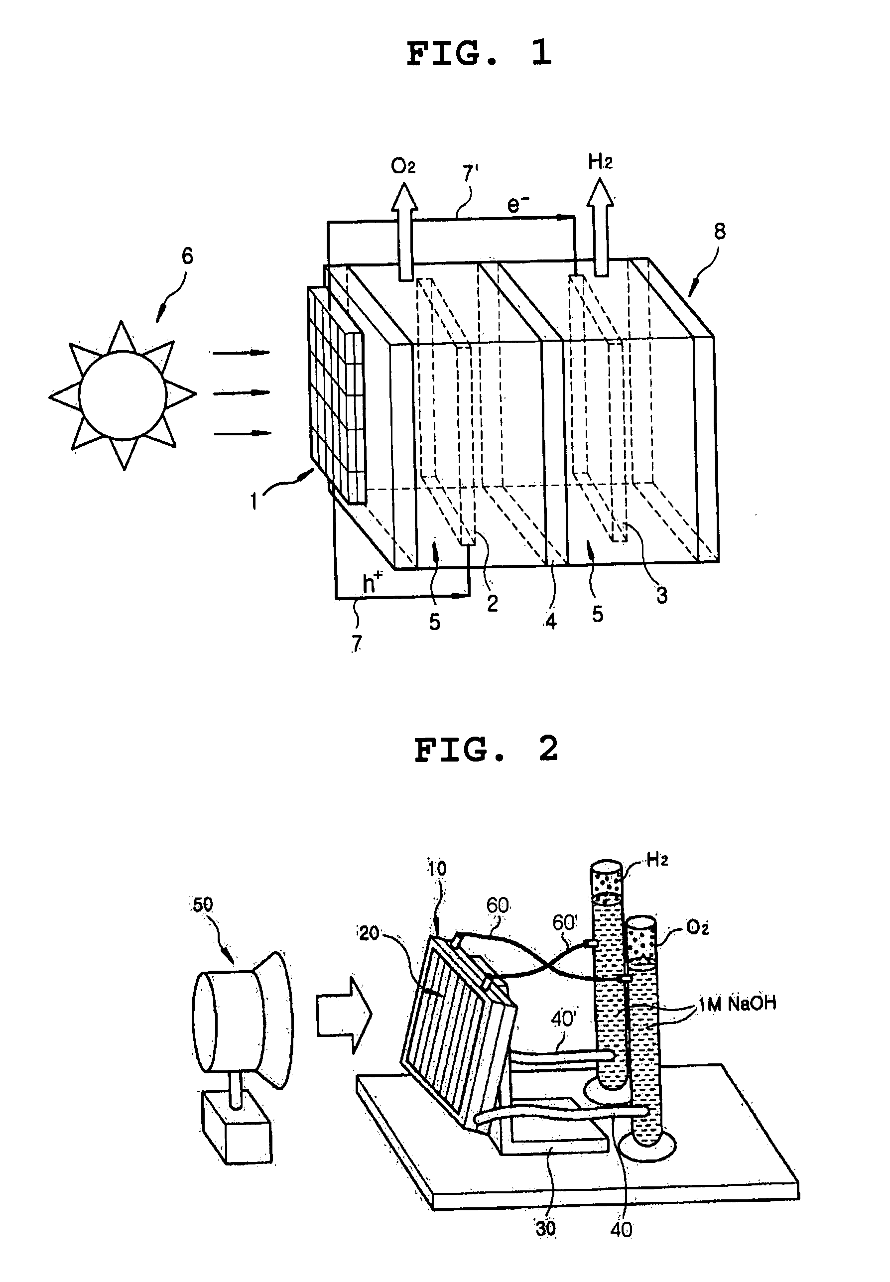
[0027]An example of the photoelectrochemical (PEC) system of the present invention shown in FIG. 2 was fabricated as described below:

[0028]Specifically, two acryl plates having the size of 12.5×12.5 cm2 were prepared. An Ni mesh which serves as an catalytic oxidation electrode, an ion exchange film capable of selectively passing OH ions, and a Pt mesh which serves as a catalytic reduction electrode (3) were placed between the two acryl plates, and the resultant was subjected to vacuum-tightening using screws to obtain a laminate (10).

[0029]To the outer surface of the laminate (10), silicon photoelectorde (20) having the size of 12.5×12.5 cm2 (Voc=2.59 V, Isc=1.582 amphere, Pmax=2.686 W) was attached using an adhesive means, and the resulting assembly was electrically connected to the two electrodes in the laminate (10) using electrical wires.

[0030]The silicon photoelectrode (20) / laminate (10) assembly was supported on a base using means (30), and 1 M NaOH aqueous electrolyte solutio...

example 2

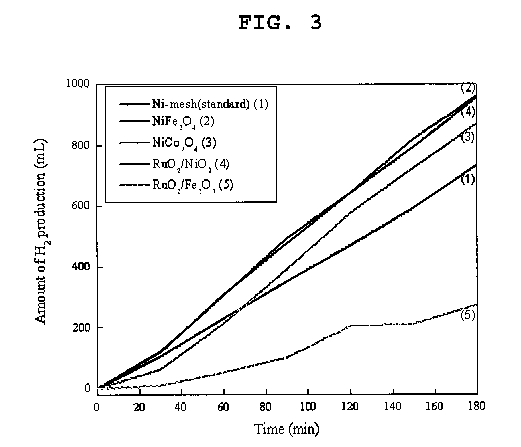
[0032]The procedure of Example 1 was repeated except that NiFe2O4, NiCo2O4, RuO2 / NiO2, and RuO2 / Fe2O3 were used instead of the Ni mesh as the catalytic oxidation electrode.

[0033]The catalytic oxidation electrodes were previously prepared by spraying an aqueous solution of nickel nitrate, iron nitrate, cobalt nitrate, or ruthenium chloride on a heated substrate, and heat-treating the resulting spray-coated substrate at 650° C. for 2 hours under an air atmosphere in a furnace.

[0034]The amounts of hydrogen produced by the PEC systems obtained using the above electrodes were measured by the same method as in Example 1, and the results are shown in FIG. 3 together with that of Example 1.

[0035]As seen from Table 1 and FIG. 3, in accordance with the present invention, hydrogen can be efficiently generated at a high yield by way of using the inventive photoelectrochemical system.

[0036]While the invention has been shown and described with respect to the preferred embodiment, it will be under...


PUM

PropertyMeasurementUnit
sizeaaaaaaaaaa
conductiveaaaaaaaaaa
optically activeaaaaaaaaaa

Abstract

The present invention provides a photoelectrochemical (PEC) system for the production of hydrogen from water, which comprises (A) an electrolytic bath comprising an electrode for catalytic oxidation, an electrode for catalytic reduction, an ion separation film disposed between the two electrodes, and an aqueous electrolyte solution into which the two electrodes and the ion separation film are immersed, and (B) a photoelectrode positioned at the outside of the electrolytic bath and electrically connected to the two electrodes. The inventive PEC system is characterized by disposing a photoelectrode at the position which does not contact aqueous electrolyte solution, thus preventing the lowering of the photoelectrode activities, and maximizing the hydrogen production efficiency.

Description

FIELD OF THE INVENTION [0001]The present invention relates to a photoelectrochemical system for producing hydrogen from water using photoelectric cells.BACKGROUND OF THE INVENTION [0002]There have been many attempts to develop a photoelectrochemical (PEC) system for producing hydrogen directly from water by photoelectrolysis using light (e.g., sunlight) as the energy source due mainly to its environmental friendly nature.[0003]PEC systems that have been studied may include tandem and hybrid cell systems. Specifically, U.S. Pat. No. 6,936,143 (Graetzel et al.) discloses a tandem cell system comprising a laminate of a conductive plate (e.g., F-doped tin dioxide), an optically active oxide layer (e.g., WO3, Fe2O3) and a dye-sensitized layer (e.g., TiO2), which is brought into contact with an aqueous electrolyte solution to produce hydrogen by photoelectrolysis of water.[0004]Further, U.S. Pat. No. 7,122,873 (Miller et al.) discloses a process for producing hydrogen by water photoelectr...

Claims


Application Information

Patent Timeline
Patent Type & Authority Applications(United States)
IPC IPC(8): H01M6/30
CPCC01B3/042H01M14/005Y02E60/366Y02E60/324Y02E60/364H01M2300/0002C25B1/55Y02E60/36Y02P20/133C01B3/00C01B3/38C25B1/04Y02E60/32
Inventor JOO, OH-SHIMJUNG, KWANG DEOGMIN, BYOUNG KOUNKIM, SOO HANGOH, JUN WOO
Owner KOREA INST OF SCI & TECH
Why Eureka
Try Eureka