Use of renewable energy like solar, wind, geothermal, biomass, and hydropower for manufacturing combustion air for a fossil fuel burner and firebox

US20080131830A1Inactive Publication Date: 2008-06-05NIX MARTIN E

Image

  • Use of renewable energy like solar, wind, geothermal, biomass, and hydropower for manufacturing combustion air for a fossil fuel burner and firebox
  • Use of renewable energy like solar, wind, geothermal, biomass, and hydropower for manufacturing combustion air for a fossil fuel burner and firebox
  • Use of renewable energy like solar, wind, geothermal, biomass, and hydropower for manufacturing combustion air for a fossil fuel burner and firebox

Examples


Embodiment Construction

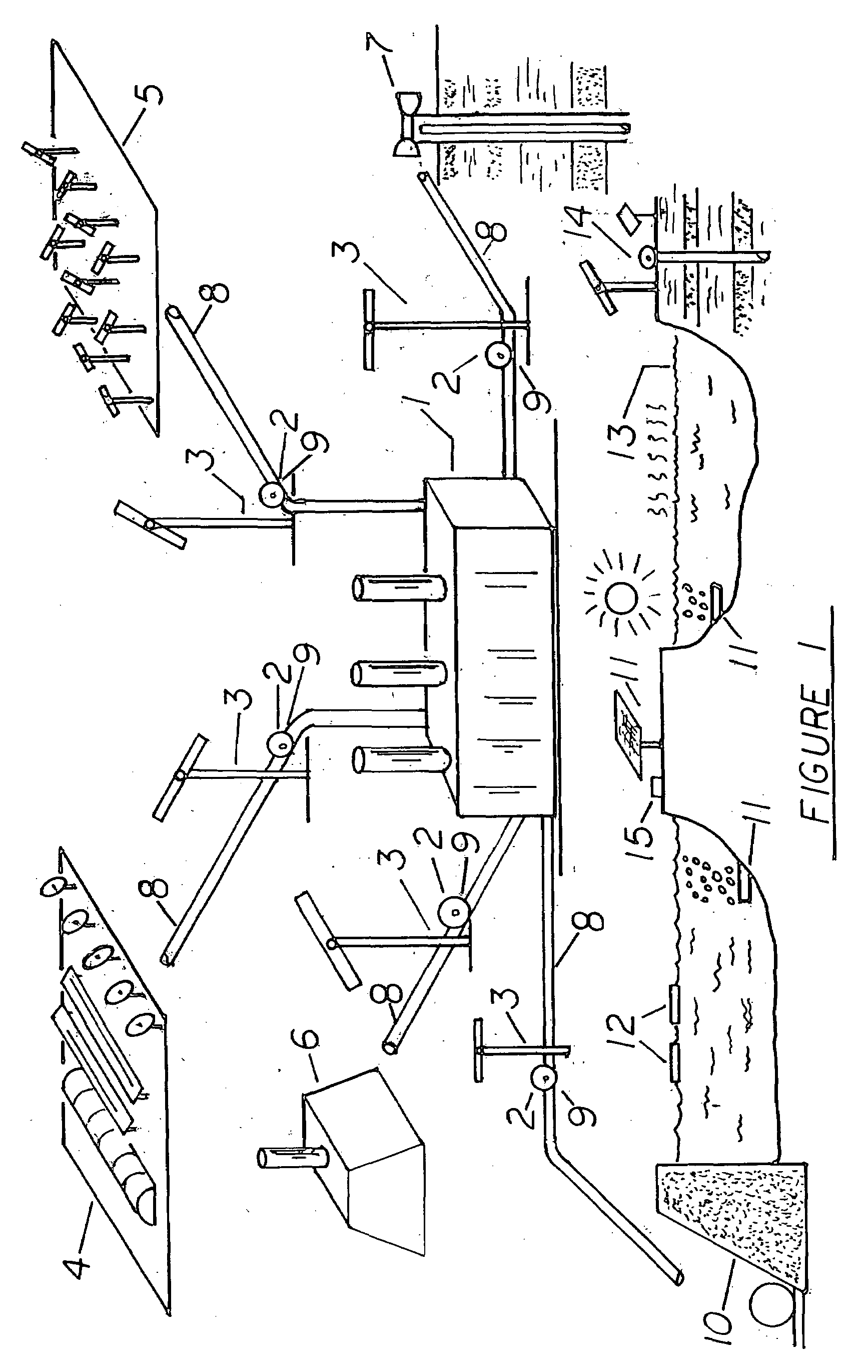
[0201]FIG. 1 illustrates an overview of the invented device. Shown is a system for manufacturing hot and compressed air for a distant power plant, like a coal burning power plant (1). Located next to the power plant could be large wind turbines (3), which power centrifuge compressors (2). From the surrounding region, various energy sources (4,5,6,7) create combustion air, and put the air into a heavily insulated pipe system (8) for long distance transmission. Along the way extra centrifuge compressors, with flywheels (9), can be located to compress and move the combustion air through the transmission system. Solar farms (4) with various types of solar collectors make and concentrate combustion air. Various types of solar collectors can be employed: solar greenhouses, sandbox solar collectors, solar ponds, evacuated tube type solar collectors, line focus and point focus type solar collectors, heliostats with towers, solar smelters, and so on. Wind energy (5) can be employed to power ...


PUM


Abstract

Invented is a method of making combustion air for a fossil fuel burner, as a coal burning power plant, oil refinery or gas fired household appliance. Combustion air is made from solar, wind, biomass, hydropower or geothermal. A staged progression using lower cost greenhouses, or flatplates, or solarponds, feed warm air to higher cost concentrator solar collectors. Wind energy, biomass, geothermal energy heat and compress combustion air. Hydropower also heats and compresses combustion air. Solar evaporation from salt or impure water creates water or local rain for the hydropower system. Combustion air thus is made economically hot, compressed and high velocity, and placed into a heavily insulated pipes for long distance transmission to a distant power plant.

Description

PRIOR ART[0001]Methods of making hot and warm air from renewable energies abound. Commonly referred to as solar, wind, biomass, or geothermal, or tidal energy; renewable energy can make hot air, compress air, and blow air. Nix in U.S. Pat. No. 5,308,187 (issued May 3, 1994) outlines a method of reducing fuel consumption for a fossil fuel burner. Air is pre-heated by solar energy, using a parking lot like surface. The transparent clear covering heats an opaque thermal conducting mass. This thermal conducting mass then transfers heat to underground pipes. The hot air is sucked into a firebox in a coal burning power plant. The pre-warmed air reduces the amount of fuel that needs to be burned. The invented device improves upon Nix, to include higher temperatures, and higher compression of the air. This makes for a more efficient combustion, reducing the amount of carbon dioxide created, and also reduces drastically the amount of fossil fuels needed.[0002]Cottle in U.S. Pat. No. 608,755 ...

Claims


Application Information

Patent Timeline
05 Jun 2008
Publication
US20080131830A1
IPC
F24H3/12
CPC
F24D5/00; Y02E10/45; F24D2200/06; F24D2200/14; F24D2200/15; F24J2/0466; F24J2/055; F24J2/07
Inventors
NIX, MARTIN E.