Micro rheometer for measuring flow viscosity and elasticity for micron sample volumes

Inactive Publication Date: 2008-06-12
RHEOSENSE
View PDF10 Cites 33 Cited by
  • Summary
  • Abstract
  • Description
  • Claims
  • Application Information

AI Technical Summary

Benefits of technology

[0009]According to the invention, viscosity and various other flow characteristics of a very small or micro sample of flowable material can be determined using a rheometer having a micro slit flow channel with monolithically integrated pressure sensors. The micro flow channel is operable with very small sample sizes and the problem of rough areas on flow channel surfaces caused by placement of individual pressure se

Problems solved by technology

But in many cases viscosity is measured under ill-defined test condition so that shear rate can not be known or calculated.
However, a “constitutive equation” is seldom known for Non-Newtonian liquids.
Therefore, true viscosity can not be measured with such ill-defined test condition for most non-Newtonian liquids.
However, because of the non-universality of the apparent viscosity measurements obtained by these systems, a correlation of the apparent viscosity of a specific sample measured with a specific method with the true viscosity has to be found separately when desired.
Therefore they are usually expensive.
Usually large amounts of sample are required for viscosity measurements with the prior art rheometers.
Further, such rheometers are not well suited for on-line applications and for high throughput measurement.
However, use of two capillaries makes the viscometers bulky or time consuming.
These viscosity measurements, however, are only simpler if

Method used


Image

  • Micro rheometer for measuring flow viscosity and elasticity for micron sample volumes
  • Micro rheometer for measuring flow viscosity and elasticity for micron sample volumes
  • Micro rheometer for measuring flow viscosity and elasticity for micron sample volumes

Examples


Embodiment Construction

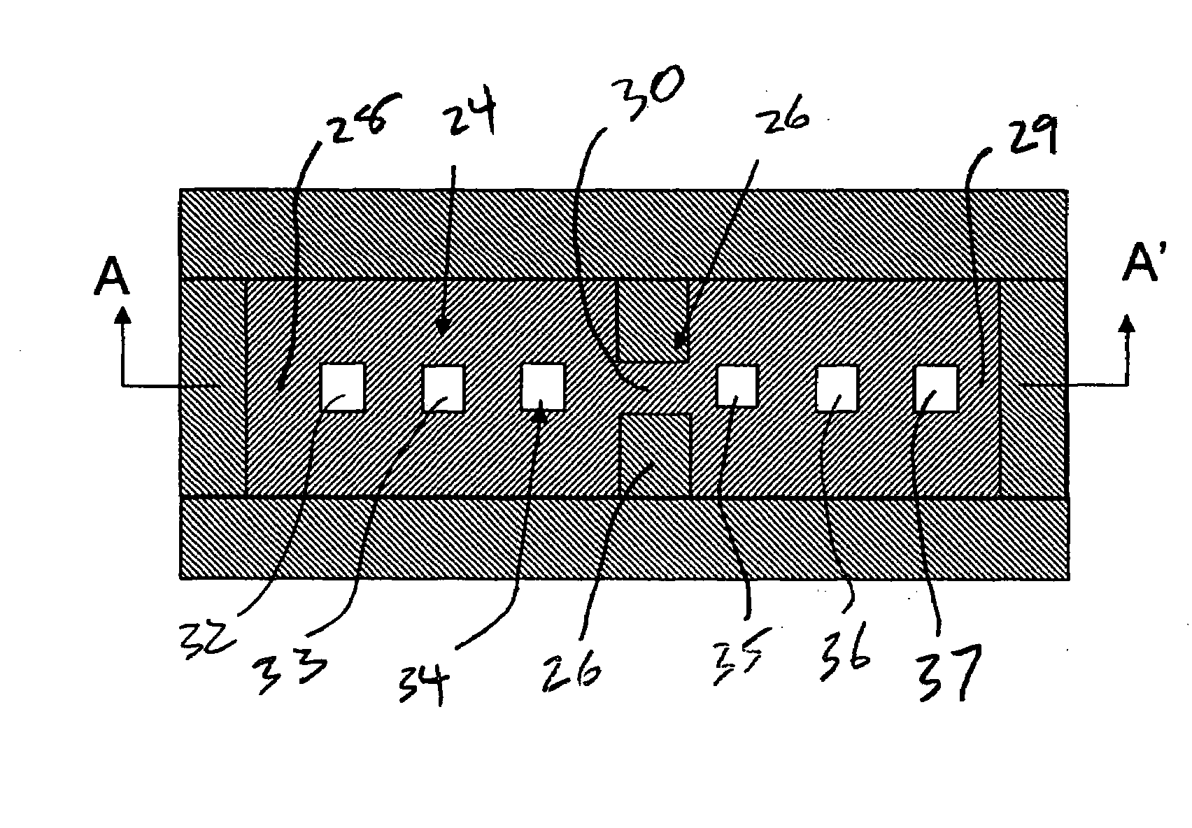
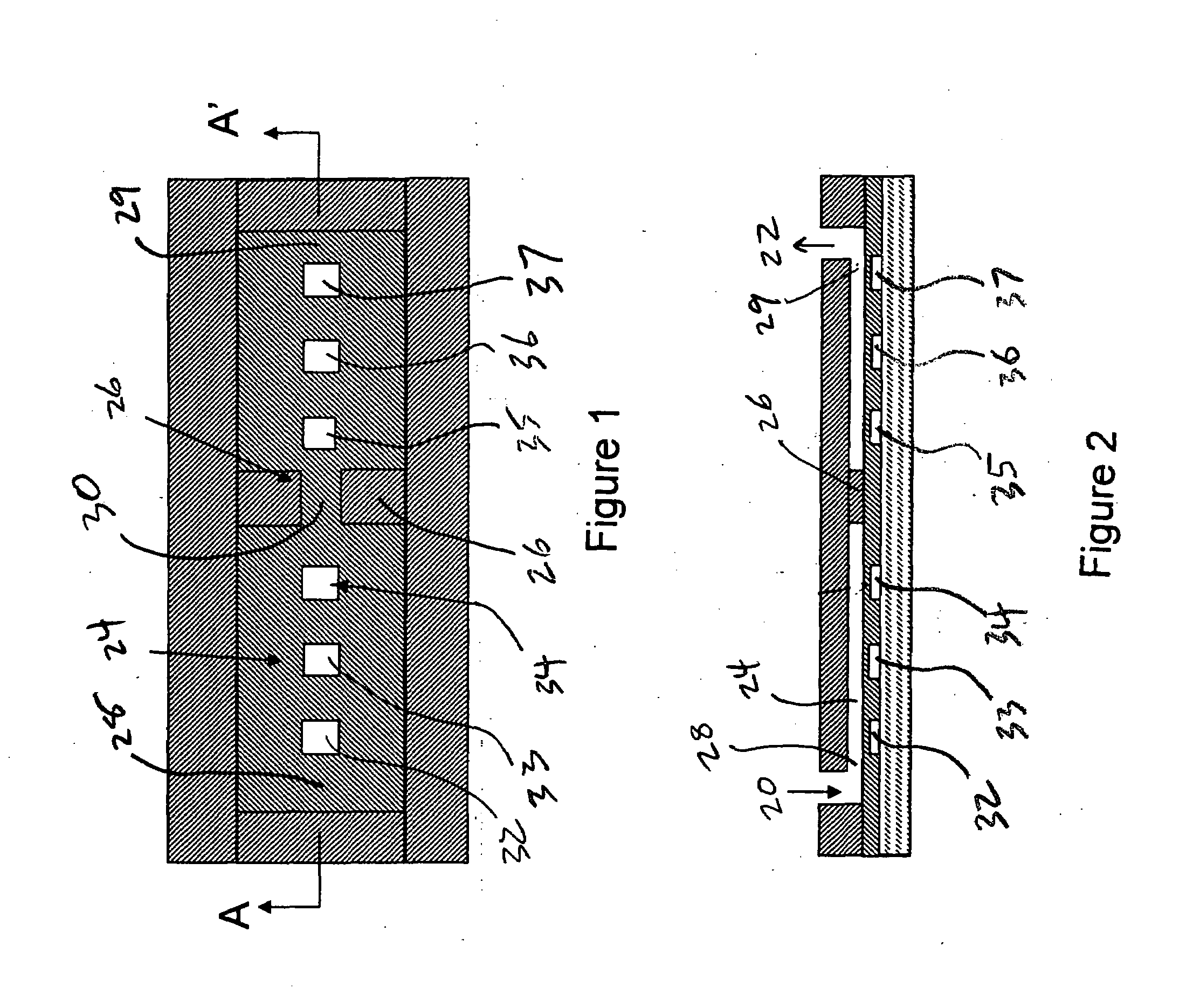
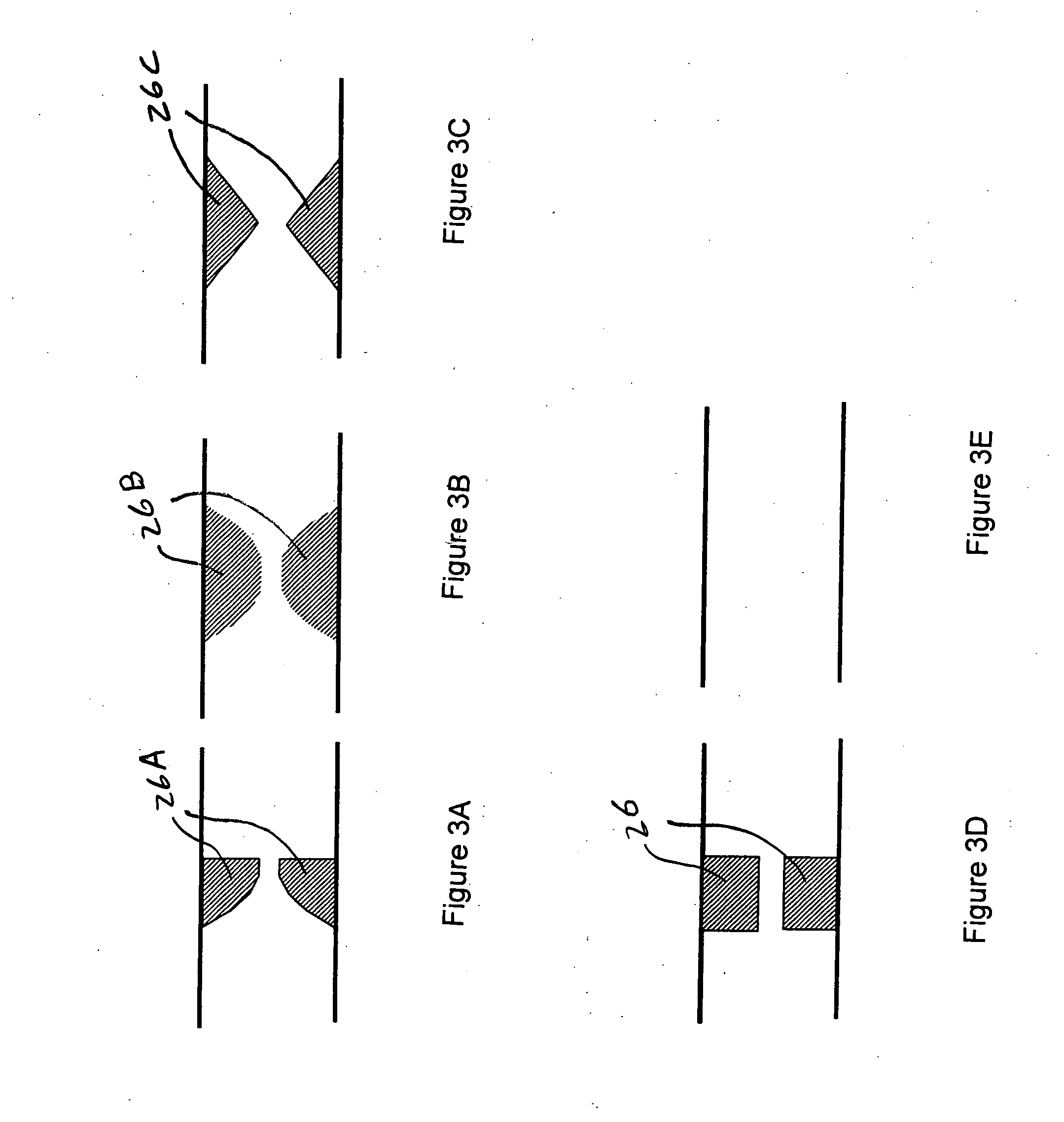
[0031]An embodiment of a micro rheometer-on-a-chip is shown in FIGS. 1 and 2 and includes a flow entrance or inlet 20, a flow exit or outlet 22, and a flow channel 24. The flow channel 24 has a predetermined channel depth (gap) in the order of micrometers along the channel and may have protrusions 26 in the intermediate portion, here shown as approximately the middle, of the length of the flow channel 24 to induce a contraction of flow of material flowing in the flow channel 24. The width of the flow channel is preferably significantly larger than the depth of the channel so that the flow through the channel can be considered to be a one-dimensional problem. The ratio of the width to the depth is preferably larger than ten. The preferred channel depth is in the order of micron. The preferred length of the channel is at least one hundred micrometers excluding the entrance and exit zones 28 and 29, respectively. In order to measure the true viscosity, the test liquid is pumped to flow...


PUM


Abstract

A micro-rheometer for measuring flow characteristics such as viscosity, elasticity, and flow rate of a sample liquid combines well defined micro-fabricated flow channels having geometry changes forming a constriction region therein to a monolithically fabricated pressure sensor arrays. The pressure sensor array positions pressure sensors to measure the viscosity of the sample liquid while flowing in a uniform length of the flow passage and to measure the extensional viscosity while flowing through the constriction region of the passage. The invention can improve the measurement accuracy of the flow rate, viscosities, or elasticities over a wide range of shear rate. The accuracy of the viscosity over a broader range of shear rate or flow rate measurement over broader range of flow rates can be accomplished by employing monolithically integrated pressure sensors fabricated with different sensitivities disposed in a known manner. The invention further includes necessary components such as a display, a pumping system, valve manifolds, and software for a portable or laboratory measurement instrument, process control, and high throughput measurements.

Description

RELATED APPLICATIONS[0001]This application is a continuation-in-part of U.S. patent application Ser. No. 11 / 078,015, filed Mar. 11, 2005, and entitled “Micro Slit Viscometer With Monlithically Integrated Pressure Sensors”, now U.S. Pat. No. 7,290,441, which was a continuation-in-part of U.S. patent application Ser. No. 10 / 286,602, filed Oct. 31, 2002, now U.S. Pat. No. 6,892,583, which claimed the benefit of provisional application Ser. No. 60 / 335,375, filed Oct. 31, 2001, both entitled “Pressure Sensing Device For Rheometers.” application Ser. No. 11 / 078,015 also claimed the benefit of U.S. Provisional Patent Application Ser. No. 60 / 552,289, filed Mar. 11, 2004, and entitled “Micro Slit Viscometer with Monolithically Integrated Pressure Sensors.” All of the above applications are incorporated herein by reference.BACKGROUND OF INVENTION[0002]1. Field[0003]This invention is in the field of miniature rheometer or viscometer devices that measure true viscosity, elasticity, or flow rate...

Claims


Application Information

Patent Timeline
IPC IPC(8): G01N11/08G01N25/00
CPCG01N11/08
Inventor BAEK, SEONG-GI
Owner RHEOSENSE
Why Eureka
Try Eureka