
Method and System for Recovering Metal from Metal-Containing Materials

a metal and metal-containing technology, applied in the field of metal recovery methods and systems, can solve the problems of increasing process costs, purex process, cost and waste generation, etc., and achieve the effect of facilitating the separation of different metals and facilitating the movement of batches

Inactive Publication Date: 2008-06-12
IDAHO RESARCH FOUNDATION INC +1
View PDF6 Cites 13 Cited by
  • Summary
  • Abstract
  • Description
  • Claims
  • Application Information

AI Technical Summary

Benefits of technology

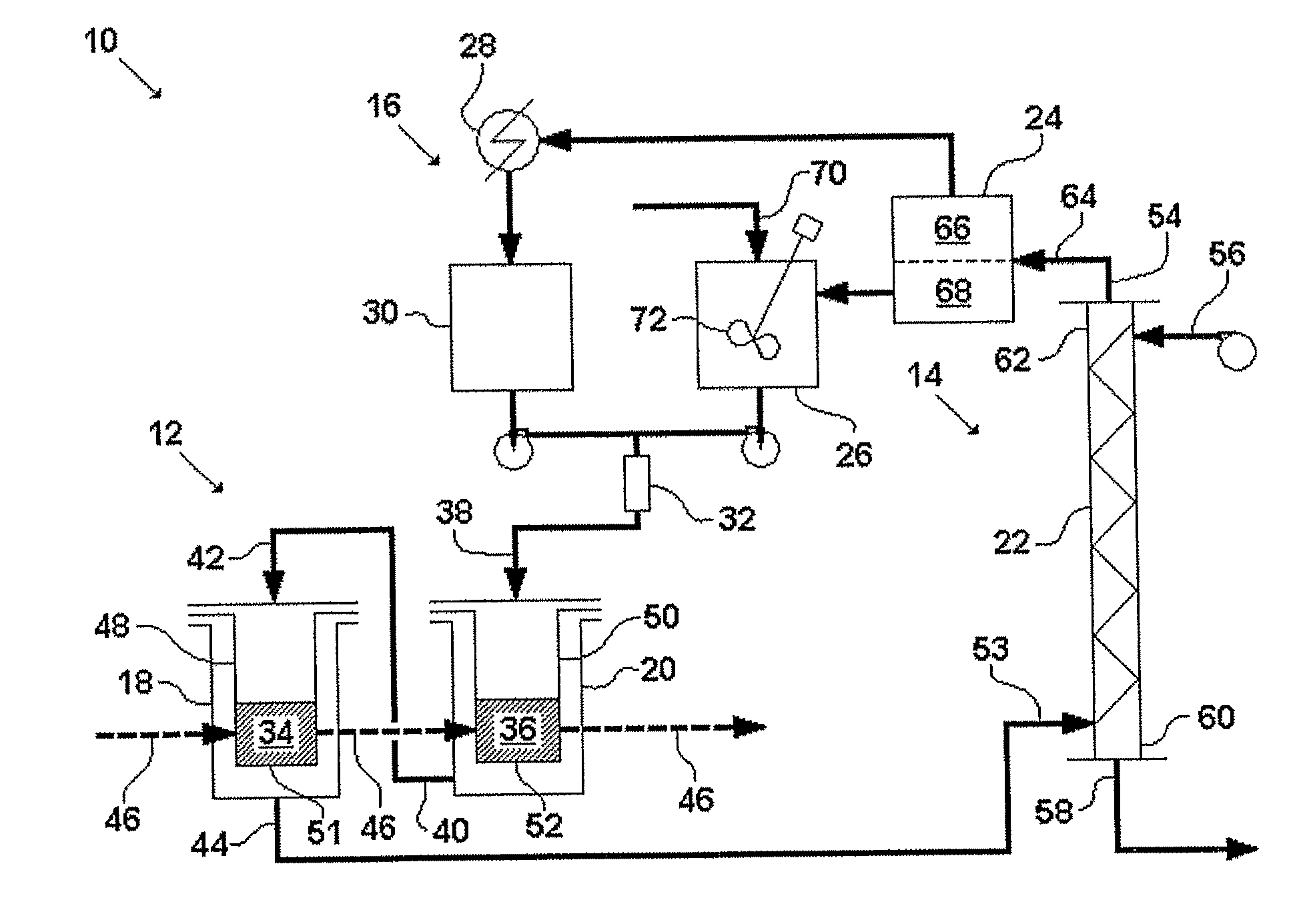
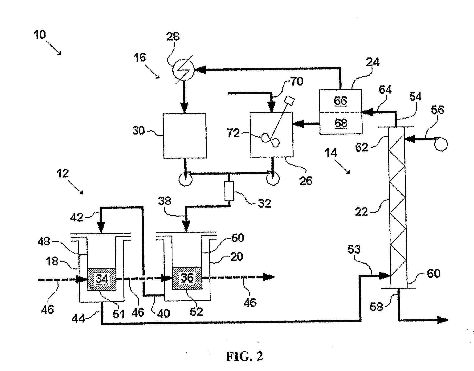
"The patent describes a method and system for extracting metals from metal-containing materials using an extractant and a stripping agent. The extractant can be a liquid or supercritical fluid solvent that forms a metal-containing complex with a complexing agent. The metal-containing material is then exposed to the extractant to form the complex. The extract is then separated from the metal-containing material in a stripping step using a countercurrent stripping process. The stripping agent can be a liquid or gas at room temperature and atmospheric pressure. The method and system can be used with various metals and waste products. The system includes an extraction device with multiple stations and an extractant-distribution network. The containers for the metal-containing material can be interchangeable between the stations. The method and system provide a continuous and efficient way to extract metals from metal-containing materials."

Problems solved by technology

The primary drawbacks of the PUREX process are cost and waste generation.
The PUREX process, for example, involves numerous liquid-liquid extractions, which increase the cost of the process and increase the amount of liquid waste.
In addition, residue left over after the nitric acid dissolution step often contains residual nitric acid and requires treatment before disposal.
The environmental and economic costs of the PUREX process vary depending on the concentration of uranium in the starting material.
Unfortunately, known processes to concentrate the uranyl nitrate solution before solvent extraction are not practical.
Factories that use uranium typically incinerate all of their combustible waste after it has been contaminated by uranium.

Method used


Image

  • Method and System for Recovering Metal from Metal-Containing Materials
  • Method and System for Recovering Metal from Metal-Containing Materials
  • Method and System for Recovering Metal from Metal-Containing Materials

Examples


example 1

[0123]This example describes several laboratory trials that were performed to study the effect of process conditions on the mass transfer of the metal in the stripping step. In these trials, the metal was uranium, the complexing agent was TBP, the oxidizing agent was nitric acid and the stripping agent was water. Tables 3-7 show the concentrations of uranium and nitric acid before stripping as well as the concentrations of uranium and nitric acid in the organic and aqueous phases after stripping. Each table shows the results of one or more trials performed at a given temperature, pressure and ratio of TBP to water. Two values for each of these variables were tested, with each table showing the data for trials performed at a different combination of values. Comparing the data between the tables indicates the effect of each variable on the mass transfer. Within each table, the individual trials represent different starting concentrations of uranium and nitric acid.

TABLE 3Stripping Dat...

example 2

[0125]This example describes one embodiment of the disclosed system. FIGS. 5-8 illustrate this embodiment in detail. FIG. 5 is a simplified schematic of the system. FIGS. 6A and 6B are a plan view and a schematic illustration of the system, respectively, with piping detail. FIGS. 7A and 7B are a plan view and a schematic illustration of the system, respectively, with dimension detail. FIG. 8 is a piping and instrumentation diagram for the system. The following abbreviations are used in the labels for certain elements in FIGS. 6-8: level control valve (LCV), pressure control valve (PCV), pump (P), safety valve (SV), and tank (TK). The labels for the remaining elements of the system are coded as shown in Table 8.

TABLE 8Key to Labels in FIGS. 6-8First LetterPpressureLlevelTtemperatureFflowHoutputSecond LetterIindicatorTtransmitterEelementSswitchYsignal converterThird LetterCcontrollerHhighLlow

[0126]A TBP-HNO3-water solution of the form TBP.(HNO3)1.8.(H2O)0.6 will be made up in TK-2 usi...

example 3

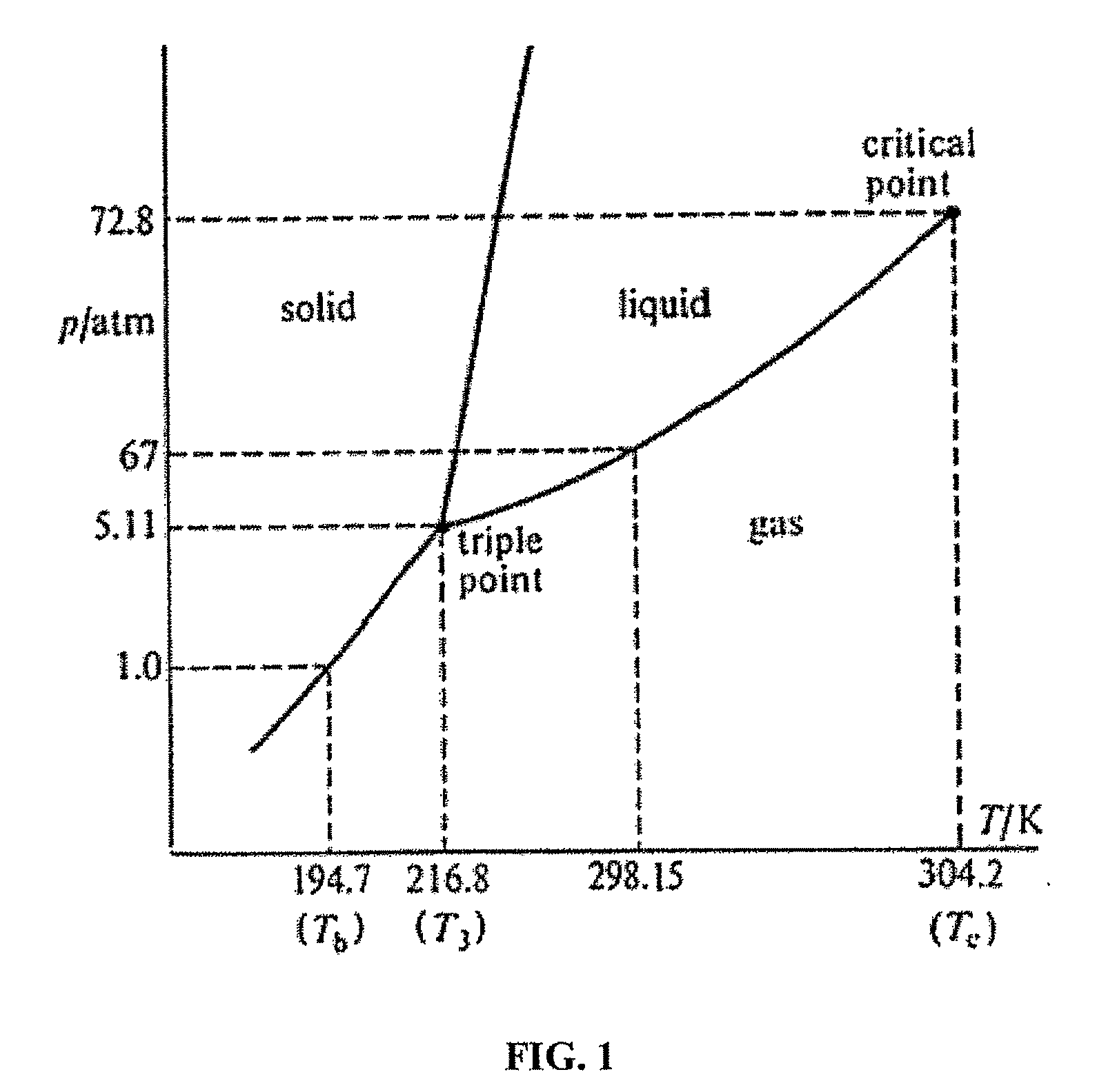
[0136]This example provides a comparison of uranium recovery by one embodiment of the disclosed process and uranium recovery by the PUREX process. Table 14 shows the initial concentration of nitric acid in the aqueous phase, the final concentration of uranium in the aqueous phase and the distribution ratio achieved in four trials modeling one embodiment of the disclosed process. The distribution ratios are equal to the concentration of uranium in the organic phase by weight divided by the concentration of uranium in the aqueous phase by weight. For the trials shown in Table 14, the uranium was extracted in supercritical carbon dioxide at 200 bar and 50° C. The ratio of TBP to water in the stripping step was 1.0.

TABLE 14Uranium Recovery with TBP in Supercritical CO2Initial ConcentrationFinal Concentration ofof HNO3 in theUranium in theDistributionTrialAqueous Phase (M)Aqueous Phase (M)RatioTrial 11.20.421Trial 24.80.115.9Trial 36.70.0669.2Trial 41.90.152.2

[0137]Table 15 shows the ini...


PUM

PropertyMeasurementUnit
internal pressuresaaaaaaaaaa

Abstract

Embodiments of a method and a system for recovering a metal, such as uranium, from a metal-containing material are disclosed. The metal-containing material is exposed to an extractant containing a liquid or supercritical-fluid solvent and an acid-base complex including an oxidizing agent and a complexing agent. Batches of the metal-containing material are moved through a series of stations while the extractant is moved through the stations in the opposite direction. After the extraction step, the metal is separated from the solvent, the complexing agent and / or other metals by exposing the extract to a stripping agent in a countercurrent stripping column. The complexing agent and the solvent exit the column and are separated from each other by reducing the pressure. The recovered complexing agent is recharged with fresh oxidizing agent and recombined with fresh or recovered solvent to form a recovered extractant, which is distributed through the extraction stations.

Description

CROSS REFERENCE TO RELATED APPLICATION[0001]This claims the benefit of the earlier filing date of U.S. Provisional Application No. 60 / 645,201, filed Jan. 18, 2005, which is incorporated herein by reference.FIELD[0002]This disclosure concerns a method and system for recovering metals, such as uranium, from metal-containing materials, particularly by extraction in a liquid or supercritical-fluid solvent.BACKGROUND[0003]A broad range of industrial processes require the separation and recovery of metal from metal-containing material. Of particular importance is the separation and recovery of uranium from uranium-containing material. Uranium-containing material is generated as a byproduct of numerous processes, mostly associated with the nuclear power industry. Two examples of waste materials that contain significant quantities of uranium are spent nuclear fuel and incinerator ash from facilities that make nuclear fuel. Due to its toxicity and potential value, recovery of uranium from th...

Claims


Application Information

Patent Timeline
Patent Type & Authority Applications(United States)
IPC IPC(8): C22B60/02C22B60/04
CPCC22B3/02C22B60/0239C22B60/026C22B60/04B01D11/0203G21C19/46C22B3/0005C01P2006/80C01G43/003B01D11/0284B01D11/0292B01D11/0288Y02P10/20Y02P20/54Y02W30/50Y02E30/30C22B3/26
Inventor WAI, CHIEN M.KOEGLER, SYDNEY S.
Owner IDAHO RESARCH FOUNDATION INC
Learn More