Method of making and structure of Multilayer Laue Lens for focusing hard x-rays

Inactive Publication Date: 2008-06-12
UCHICAGO ARGONNE LLC
View PDF1 Cites 19 Cited by
  • Summary
  • Abstract
  • Description
  • Claims
  • Application Information

AI Technical Summary

Benefits of technology

[0013]In brief, a zone plate multilayer structure and method of making a Multilayer Laue Lens (MLL) for focusing hard x-rays are provided. The zone plate multilayer structure includes a substrate carrying a plurality of alternating layers respectively formed of tungsten silicide (WSi2) and silicon (Si). The alternating layers are sequentially deposited precisely controlling the thickness of each layer from a minimum thickness of a first deposited layer adjacent the substrate to a maximum thickness of a last deposited layer. The first minimum thickness layer has a selected thickness of less than or equal to 5 nm with the thickness of the alternating layers monotonically increasing to provide a zone plate multilayer structure having a thickness of greater than 12 μm (microns).
[0014]The multilayer structure is sliced and polished to many sections with desired dimensions. Each section can be used as a partial linear zone plate to focus hard x-rays to a line. The x-rays are diffracted in Laue transmission geometry by the specific arrangement of silicon and tungsten silicide. Two such sections crossed focus the x-rays to a point. The sections are tilted at an optimum angle for high diffraction efficiency. For example, highest efficiency is achieved with the layers in the multilayer sections are tilted towards the Bragg angle of diffraction. Ideally, four such sections can be used to form a complete MLL. A two-section pair focuses the x-rays to a line and two pairs crossed focus the x-rays to a p

Problems solved by technology

For efficient focusing of hard x-rays, a very large aspect ratio is required, which presents a formidable challenge for the manufacturing

Method used


Image

  • Method of making and structure of Multilayer Laue Lens for focusing hard x-rays
  • Method of making and structure of Multilayer Laue Lens for focusing hard x-rays
  • Method of making and structure of Multilayer Laue Lens for focusing hard x-rays

Examples


Embodiment Construction

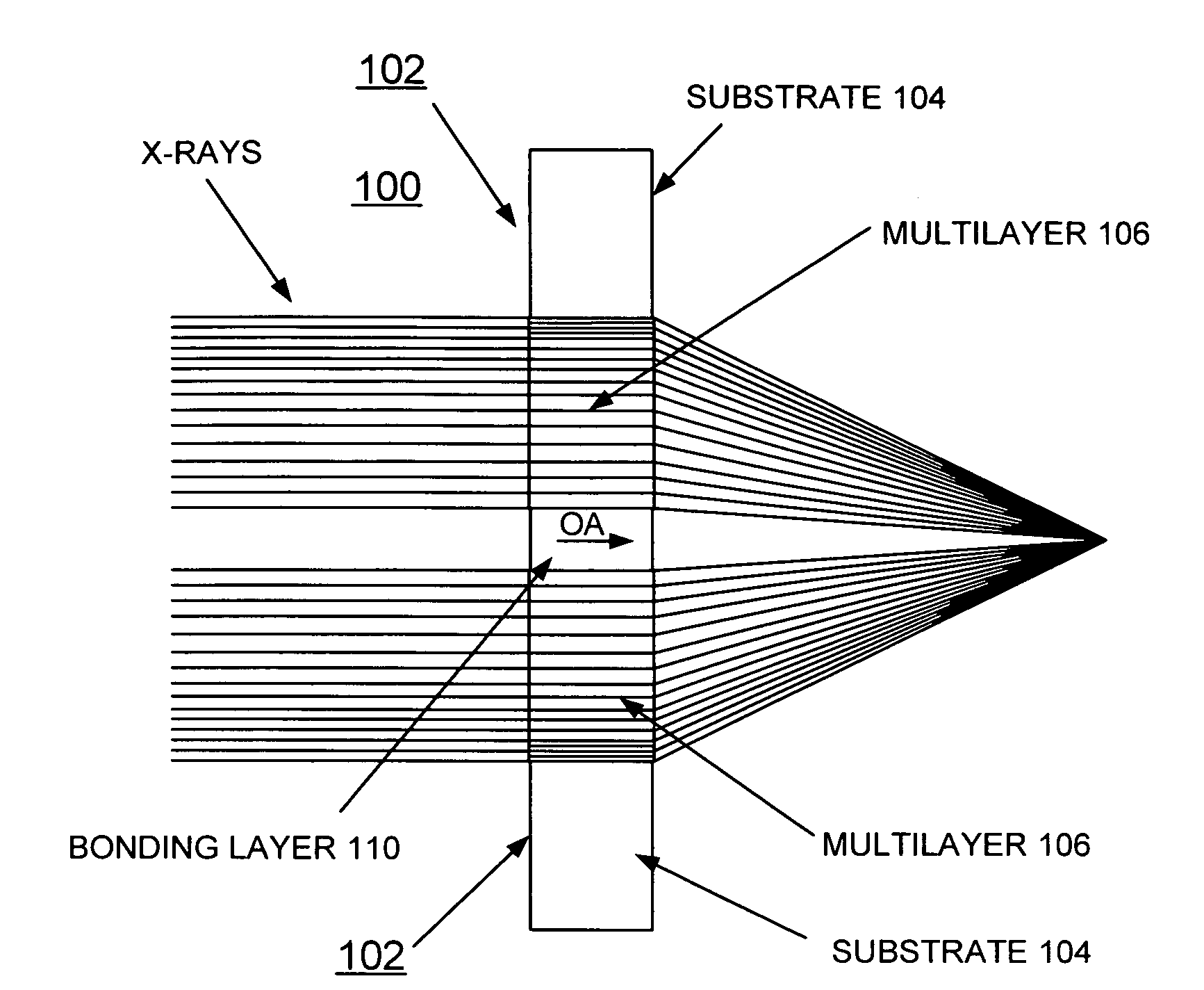
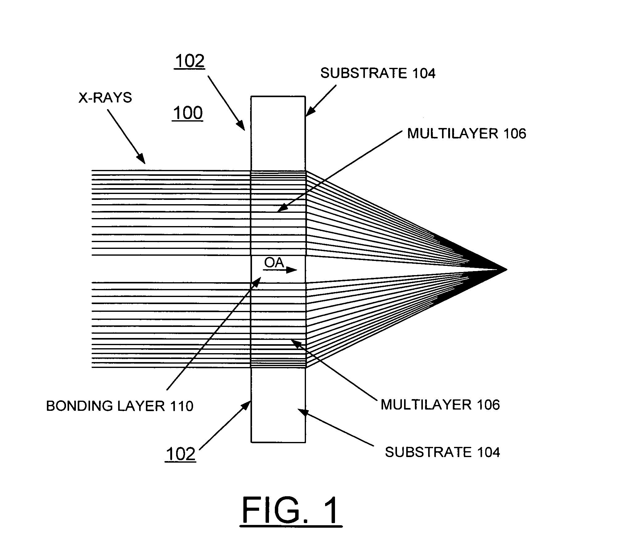
[0023]In accordance with features of the invention, fabrication of linear zone plates is achieved using sputtered-sliced planar multilayers made of selected materials. The fabrication of zone plates by alternative techniques of the invention surmounts some prior art limitations. A growth of a multilayer film to be used in transmission or Laue diffraction geometry is provided, in which the thickness of consecutive layers gradually increases according to the Fresnel zone formula. The film is sectioned after growth to the required depth. For a planar multilayer, this produces a linear zone plate that can focus x-rays substantially in one dimension.

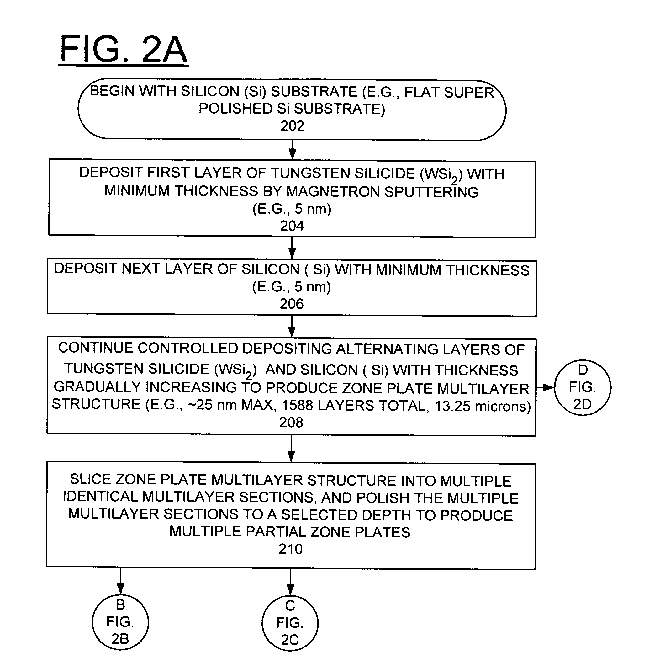
[0024]In accordance with features of the invention, a method of making a Multilayer Laue Lens (MLL) zone plate includes the deposition and sectioning of a multilayer consisting of high-Z and low-Z layers, where Z is the electron density. The thickness of deposited films can be controlled in the Angstrom range much more precisely than the x-y ...


PUM


Abstract

A zone plate multilayer structure includes a substrate carrying a plurality of alternating layers respectively formed of tungsten silicide (WSi2) and silicon (Si). The alternating layers are sequentially deposited precisely controlling a thickness of each layer from a minimum thickness of a first deposited layer adjacent the substrate to a maximum thickness of a last deposited layer. The first minimum thickness layer has a selected thickness of less than or equal to 5 nm with the thickness of the alternating layers monotonically increasing to provide a zone plate multilayer structure having a thickness of greater than 12 μm (microns). The x-rays are diffracted in Laue transmission geometry by the specific arrangement of silicon and tungsten silicide.

Description

CONTRACTUAL ORIGIN OF THE INVENTION[0001]The United States Government has rights in this invention pursuant to Contract No. W-31-109-ENG-38 between the United States Government and The University of Chicago and / or pursuant to Contract No. DE-AC02-06CH11357 between the United States Government and UChicago Argonne, LLC representing Argonne National Laboratory.FIELD OF THE INVENTION[0002]The present invention relates to an improved apparatus and method of making the apparatus for sharper focusing of hard x-rays; and more specifically, relates to a Multilayer Laue Lens (MLL) zone plate for focusing of hard x-rays and a method of making the MLL zone plate.DESCRIPTION OF THE RELATED ART[0003]Modern synchrotron-radiation facilities provide unprecedented levels of intensity and collimation in x-ray beams and offer tremendous research opportunities. The development of improved x-ray focusing optics is essential for further advances in x-ray microimaging and microanalysis applications.[0004]...

Claims


Application Information

Patent Timeline
IPC IPC(8): G21K1/06
CPCB82Y10/00G21K2201/067G21K2201/061G21K1/062
Inventor LIU, CHIAN Q.CONLEY, RAYMOND P.MACRANDER, ALBERT T.KANG, HYON CHOLSTEPHENSON, G. BRIANMASER, JORG
Owner UCHICAGO ARGONNE LLC
Why Eureka
Try Eureka