Method for irradiating objects

a technology of irradiation and objects, applied in the field of food packaging industry, can solve the problems of difficult to make the electrons travel long, energy is absorbed, and the energy supplied to the system is lost, and achieve the effect of shortening the tim

Inactive Publication Date: 2008-06-12
TETRA LAVAL HLDG & FINANCE SA
View PDF3 Cites 32 Cited by
  • Summary
  • Abstract
  • Description
  • Claims
  • Application Information

AI Technical Summary

Benefits of technology

[0010]Therefore, an object of the invention has been to provide a method for irradiating objects with electron beam irradiation with which the irradiation will be made in shorter time and with which the dose will be uniform.

Problems solved by technology

However, a disadvantage using irradiation is that much of the energy supplied to the system is lost when the electrons hit molecules in the surrounding environment (such as the air) and the energy is absorbed.
Because of that it is difficult to make the electrons travel long distances, and therefore it is also sometimes difficult to provide a uniform electron beam dose to the object to be irradiated.
It may for example sometimes be difficult to reach the portions of the object located most distant the electron beam generator.
Further, to obtain a sufficient irradiation level, the irradiation time has to be relatively long.
This is inefficient from two perspectives.
Firstly, the production time is affected, and in high speed production a long irradiation time is of course a disadvantage.
Secondly, the longer irradiation time the more energy is used, and this considerably affects the cost.

Method used


Image

  • Method for irradiating objects
  • Method for irradiating objects
  • Method for irradiating objects

Examples


second embodiment

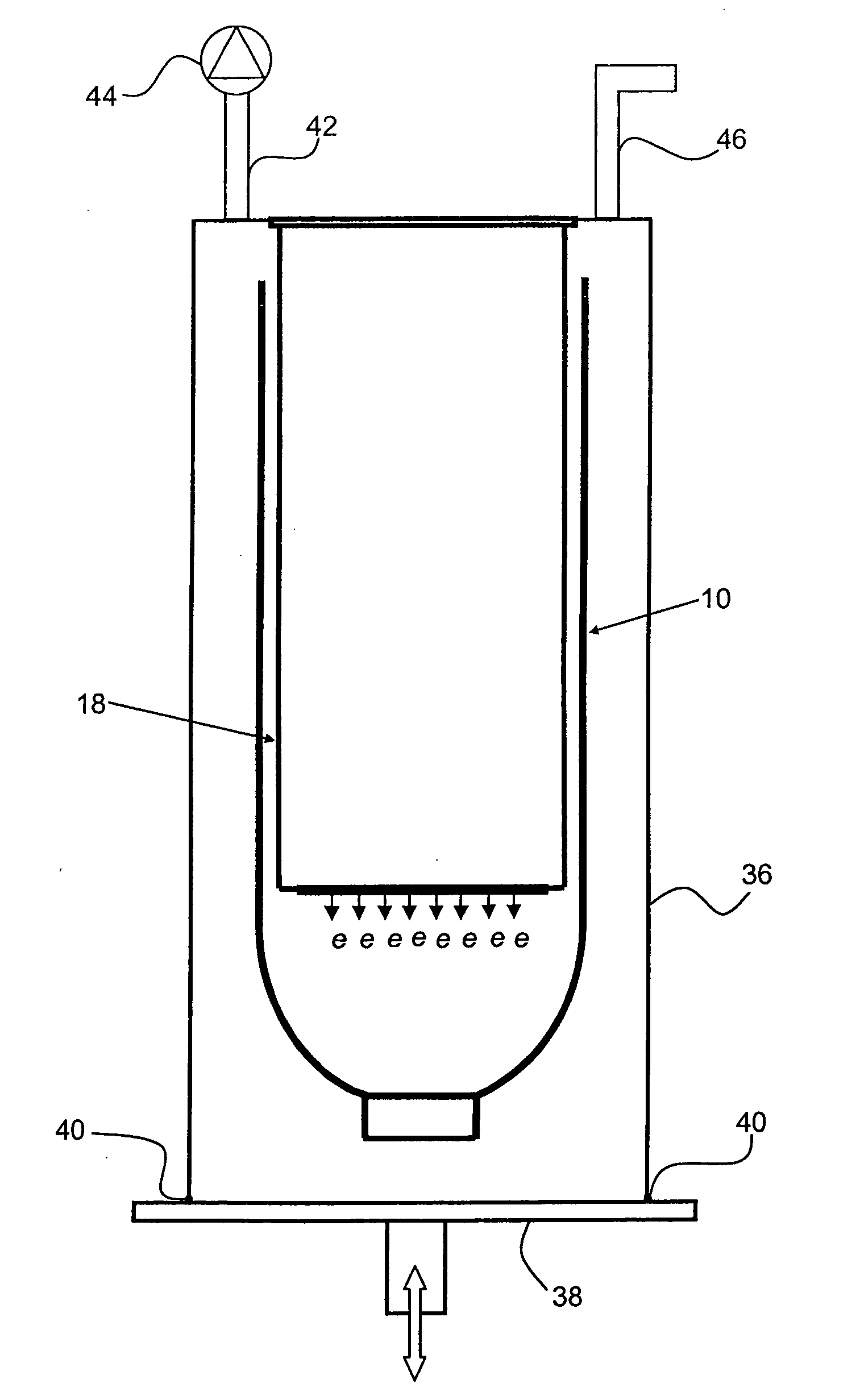
[0067]FIG. 4 shows a device for irradiation of partly formed packages 10 in a packaging machine. The figure shows a schematic sterilization unit 48 comprising an irradiation chamber 36 and a filling chamber 50. The sterilization unit 48 comprises a conveyor 52 which is adapted to transport packages 10 through the unit 48. The arrow B illustrates the conveying direction. First the packages 10 are transported through the irradiation chamber 36 to be sterilized and then through the filling chamber 50 to be filled with a product. Said filling chamber 50 can be part of any suitable type of package filling system. For example a linear filling system or a rotary filling system can be used. The filling system will not be described in more detail. After filling the packages 10 are conveyed further to a sealing station where the packages are sealed in their still open end 14.

[0068]Further, there is provided means 44 for enabling a pressure regulation. In this case the pressure regulation cons...

fourth embodiment

[0079]FIG. 6 shows such the device.

[0080]The web 60 is continuously conveyed through the irradiation chamber 36 by any conventional conveying means (not shown). In this embodiment the chamber is a narrow tunnel 36. The web 60 is passed past at least one sterilizing device 18. In this case the web 60 is passed between two electron beam sterilizing devices 18, one on each side of the web, for double-sided irradiation. The web transportation direction is illustrated by the arrow A. For details on the overall design of an exemplary device reference is made to the international patent publications WO 2004 / 110868 and WO 2004 / 110869.

[0081]The tunnel 36 is enclosing a gaseous environment having a first pressure.

[0082]Downstream and upstream the electron beam sterilizing devices 18 the device is provided with means 62 for keeping a pre-determined second pressure at least in the environment nearest the sterilizing device 18 during irradiation of the web 60. In this example these means 62 are ...


PUM

PropertyMeasurementUnit
voltageaaaaaaaaaa
accelerating voltageaaaaaaaaaa
kinetic (motive) energyaaaaaaaaaa

Abstract

The invention relates to a method for irradiating partly formed packages (10) with electron beam irradiation from at least one electron beam sterilizing device (18), characterized in that it comprises: providing at least one partly formed package (10) to be irradiated in a gaseous environment, and exposing the gaseous environment to a pre-determined pressure regulation cycle and exposing the partly formed package (10) to irradiation at least during a portion of said pressure regulation cycle. The invention also relates to a device for realizing said method. The invention further relates irradiation of a packaging material web.

Description

[0001]The present invention refers to a method and a device for irradiating objects such as partly formed packages and packaging material webs with electron beam irradiation.TECHNICAL BACKGROUND[0002]Within the food packaging industry it has for a long time been used packages formed from a web or a blank of packaging material comprising different layers of paper or board, liquid barriers of for example polymers and gas barriers of for example thin films of aluminium. Another type of packages that are used in the food packaging industry is packages made from polymer material and manufactured through for example blow-moulding.[0003]To extend the shelf-life of the products being packed it is prior known to sterilize the web before the forming and filling operations, and to sterilize the partly formed packages (ready-to-fill packages, RTF packages) before the filling operation. Depending on how long shelf-life is desired and whether the distribution and storage is made in chilled or amb...

Claims


Application Information

Patent Timeline
Patent Type & Authority Applications(United States)
IPC IPC(8): A61L2/08B65B55/08
CPCA61L2/087A61L2202/122A61L2202/23B67C2003/228B65B55/10B67C7/00B65B55/08A61L2/08
Inventor KRISTIANSSON, ANDERSNASLUND, LARS AKE
Owner TETRA LAVAL HLDG & FINANCE SA
Why Eureka
Try Eureka